Eureka AIR delivers breakthrough ideas for toughest innovation challenges, trusted by R&D personnel around the world.

Model-based battery fuel gauges and methods

Active Publication Date: 2012-06-12
MAXIM INTEGRATED PROD INC
View PDF12 Cites 26 Cited by
  • Summary
  • Abstract
  • Description
  • Claims
  • Application Information

AI Technical Summary

Problems solved by technology

Such devices are useful for the intended purpose, though have certain characteristics that are less than ideal.
Since battery fuel gauges typically are designed to operate on relatively low sense voltages, the voltage drop across the current sense resistor in series with the battery need not be large, though still that voltage drop represents a loss of battery voltage and power available to the circuitry powered by the battery, as well as power dissipation (heating) in the resistor itself.
Normally, such resistors are discrete components, a disadvantage itself, particularly in battery powered devices such as laptop computers and cell phones where circuit area and cost are to be held to a minimum.
Another undesirable characteristic of such battery fuel gauges is the fact that they essentially operate as integrators, and as such, their output at any time is subject to an accumulation of integration errors since the last time they were set to a reference.
Accordingly, such battery fuel gauges work satisfactorily when a battery is regularly fully charged, or alternatively, fully discharged, to provide the reference, but do not perform well if the battery is repeatedly only partially charged and partially discharged.
This, of course, has the advantage of simplicity and avoidance of the requirement of a current sense resistor in series with the battery, though has the disadvantage of not providing an ongoing indication of the state of charge of the battery because of not considering the load on the battery at the time of the indication.

Method used


Image

  • Model-based battery fuel gauges and methods
  • Model-based battery fuel gauges and methods
  • Model-based battery fuel gauges and methods

Examples


Embodiment Construction

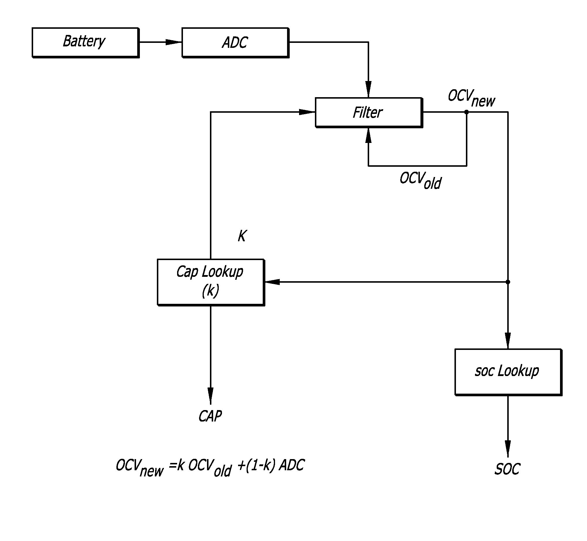
[0020]The preferred embodiments of the present invention do not use a current sense resistor, but instead are preferably effectively connected directly across the battery terminals, typically by being connected directly across circuit connections which themselves connect directly to the battery terminals when the battery is in the battery operated device. As shall be subsequently discussed, the connection of the battery fuel gauge may be before or after the on / off switch for the device so as to either be constantly powered or powered only when the device itself is powered. In one preferred embodiment, the battery fuel gauge is always powered so long as the battery is in the battery powered device, as the power consumption of the battery fuel gauge is only a small fraction of the battery self discharge rate for the battery.

[0021]In essence, the battery fuel gauges of the present invention model the battery itself, and as shall be seen, track the state of charge of the battery indepen...


PUM


Abstract

Model-based battery fuel gauges that connect across a rechargeable battery and track the per-cent state of charge of the battery. The model based fuel gauges provide a measure of the open terminal voltage of a battery, even when the battery is powering a load, to provide the state of charge information. Analog and digital implementations of the battery model fuel gauges may be used, and incorporated into a battery powered device in various ways, including constantly powered implementations and implementations that are turned on and off with the battery powered device. Various exemplary embodiments are disclosed.

Description

CROSS-REFERENCE TO RELATED APPLICATION[0001]This application is a continuation of U.S. patent application Ser. No. 11 / 638,999 filed Dec. 13, 2006.BACKGROUND OF THE INVENTION[0002]1. Field of the Invention[0003]The present invention relates to battery fuel gauges for indicating the state of charge or discharge, typically of a rechargeable battery.[0004]2. Prior Art[0005]As used herein, the word battery will be used generally, and is to be understood to include multiple batteries and battery packs, that is, multiple batteries packaged and electrically connected to functionally appear as a single battery of a higher voltage and / or higher current capacity.[0006]In many rechargeable battery powered devices, it is desirable to know the state of charge (or discharge) of the battery during its discharge cycle so that the user of the battery powered device can appropriately time the recharging of the battery, and when necessary, limit the use of the battery powered device to more essential u...

Claims


Application Information

Patent Timeline
IPC IPC(8): H02J7/00
CPCG01R31/3624G01R31/3651H01M10/488H02J7/0021G01R31/3842G01R31/367Y02E60/10H02J7/0048H02J7/0014
Inventor WORTHAM, JASON ALLEN
Owner MAXIM INTEGRATED PROD INC
Why Eureka
Eureka Blog
Learn More