Bias controller

a bias controller and controller technology, applied in the field of bias controllers, can solve the problems of bias point, prone to drift, and inconsistent optical output level of the modulator,

Active Publication Date: 2012-06-19
BAE SYSTEMS PLC
View PDF11 Cites 50 Cited by
  • Summary
  • Abstract
  • Description
  • Claims
  • Application Information

AI Technical Summary

Problems solved by technology

There are various reasons why during operation of a Mach-Zehnder electro-optic modulator a given modulating voltage level will result in a slightly inconsistent optical output level from the modulator.
That is, the bias point—the voltage that needs to be applied to a bias electrode for example in order to return the modulator to or near a quadrature point—is prone to drift over time.
Temperature variations in particular are likely to result in physical changes to the length of the interferometer in a Mach-Zehnder modulator for example, with consequent variations in the bias point.
Such a modulator is still, however, temperature-sensitive: any variation in temperature changes the length of the interferometer.

Method used


Image

  • Bias controller
  • Bias controller
  • Bias controller

Examples


Embodiment Construction

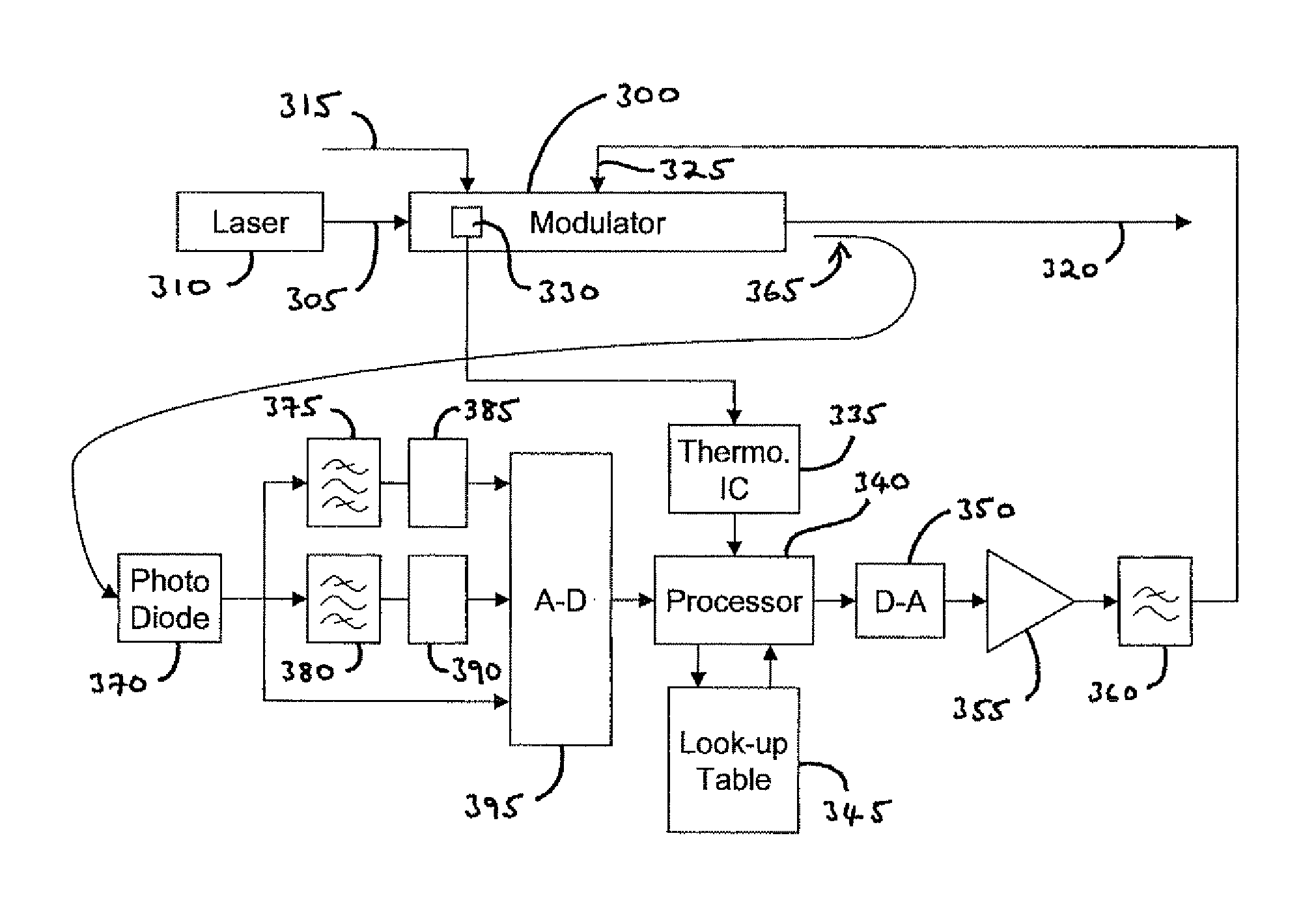
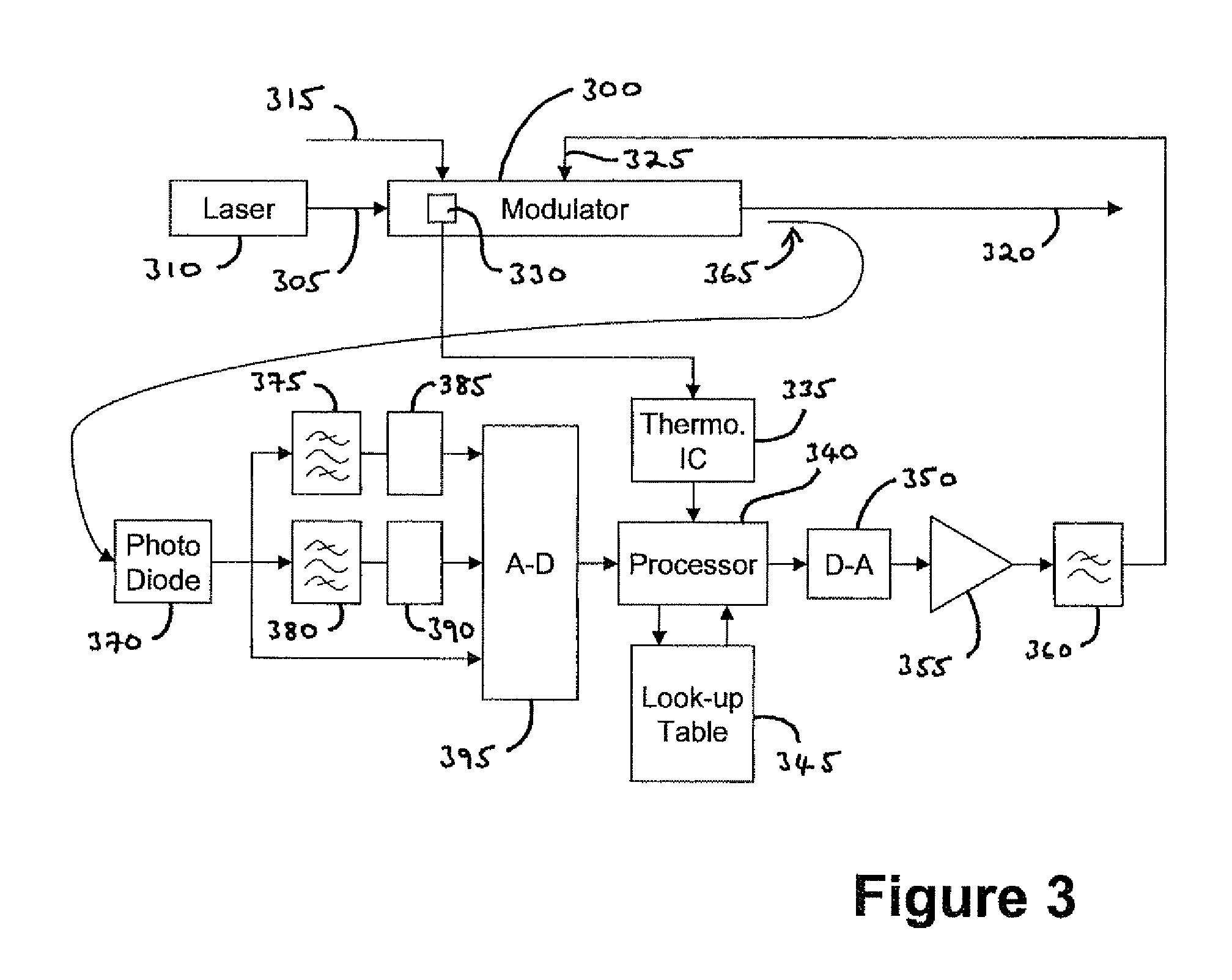
[0037]Exemplary embodiments of the present invention will now be described in more detail, by way of example only, with reference to the accompanying drawings.

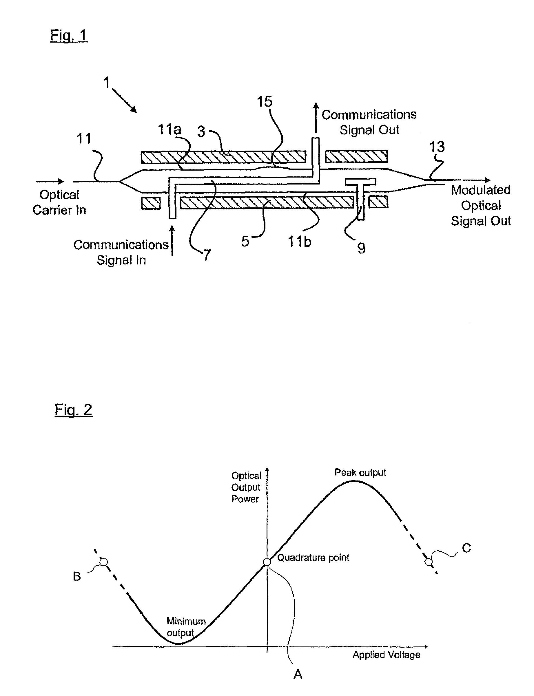
[0038]An exemplary embodiment of the present invention will now be described in the context of a Mach-Zehnder Interferometer (MZI) modulator for which it is assumed that the bias point is electrically stable over time and that the only significant cause of bias point drift during operation of the modulator are effects due to temperature variation. An outline of the structure and principles of operation of an MZI modulator will firstly be provided with reference to FIG. 1 and to FIG. 2.

[0039]Referring firstly to FIG. 1, an illustrative schematic representation is provided of a known MZI modulator 1 of the type that is often employed in optical communications systems.

[0040]MZI modulators provide a mechanism whereby an input optical carrier signal may be modulated with a communications signal, for example with an RF communication...


PUM


Abstract

A bias controller and a method for controlling the bias of an electro-optic modulator are provided. In the method, for a received indication of modulator temperature, steps are provided for accessing a look-up table to determine a corresponding value of bias voltage, for a required bias point, to apply to the modulator. If no such value is stored, additional steps are provided to generate a pilot tone for input to the modulator and to recognize, from the signal content of a modulated optical signal output by the modulator, operation of the modulator at the required bias point, adjusting the value of bias voltage being applied to the modulator as required. When operation at the required bias point is recognized, the respective value of bias voltage for that modulator temperature is stored in the look-up table. The same method is provided to configure a bias controller in respect of a given modulator, if necessary ab initio.

Description

RELATED APPLICATION INFORMATION[0001]This application is a United States National Phase Patent Application of International Patent Application No. PCT / GB2008 / 051083 which was filed on Nov. 19, 2008, and claims priority to British Patent Application No. 0723650.8, filed on Dec. 4, 2007, and claims priority to European Patent Application No. 07270069.3, filed on Dec. 4, 2007, the disclosures of each of which are incorporated herein by reference.FIELD OF THE INVENTION[0002]This invention relates to bias controllers, in particular, but not exclusively, to a bias controller for electro-optic modulators, for example for so-called Mach-Zehnder modulators. Such modulators have utility, in particular, in the field of optical communications systems.BACKGROUND INFORMATION[0003]It is known, in particular for Mach-Zehnder electro-optic modulators, for it to be necessary in certain applications to make periodic adjustments to biasing of the modulator to ensure that it continues to operate at or n...

Claims


Application Information

Patent Timeline
Patent Type & Authority Patents(United States)
IPC IPC(8): G02B26/00H04B10/50
CPCG02F1/0123H04B10/505G02F2203/60
Inventor SMITH, ANDREW JAMESNAWAZ, MOHAMMED
Owner BAE SYSTEMS PLC
Why Eureka
Try Eureka