
Smoke detector testing tool

a technology for testing tools and smoke detectors, applied in the direction of measuring devices, scientific instruments, instruments, etc., can solve the problems of many avoiding such testing, additional time and effort, and other maintenance and testing functions performed at smoke detectors, such as cleaning, magnetic adapter testing, etc., to achieve the effect of avoiding the problem of wasting time and effor

Inactive Publication Date: 2012-06-26
HALLISEY RICHARD D
View PDF15 Cites 22 Cited by
  • Summary
  • Abstract
  • Description
  • Claims
  • Application Information

AI Technical Summary

Benefits of technology

[0021]Still a further object of the smoke detector testing tool provides a spring that aids in removal and replacement of a spent smoke container or spent air container.
[0033]Still a further aspect of the smoke detector testing tool comprises a case lid comprising particular inner rectangular dimensions so as to fit snuggly over a mating perimeter edge of the case body. The case body and case lid further comprise conventional expected features such as a grasping case handle, a latching case lid hasp, and a pair of common metal axle hinges. Said case body and case lid provide protection to included attachments via an internal fill / padding portion comprising a specific profile and depth so as to emulate particular attachments and providing a snug padded fit.

Problems solved by technology

While just about all units provide a test button, the only sure way of testing such devices is with the use of real smoke.
This additional complication leads to additional time and effort thus causing many to skip such testing.
Other maintenance and testing functions performed at smoke detectors including cleaning, testing of magnetic adapters, access to bar codes, and the like also face the same difficulties.
Unfortunately, this patent does not appear to disclose a smoke detector testing device that comprises a smoke dispensing assembly and an air dispensing assembly to purge the smoke from the detectors, nor does this patent appear to disclose a mechanical or magnetic probe to test the detector's buttons and / or switches.
Unfortunately, this patent does not appear to disclose a smoke detector testing tool that comprises a magnetic or mechanical probe for testing switches and / or buttons on the detector, nor does it appear to disclose a smoke detector testing tool that through a plurality of extension tubes is capable testing smoke detectors mounted high on walls.
Unfortunately, this patent does not appear to disclose a smoke detector testing device that comprises a smoke dispensing assembly and an air dispensing assembly to purge the smoke from the detector, nor does this patent appear to disclose a mechanical or magnetic probe to test the detector's buttons and / or switches.
Unfortunately, this patent does not appear to disclose a smoke detector testing tool that comprises a magnetic or mechanical probe for testing switches and / or buttons on the detector, nor does it appear to disclose a smoke detector testing tool that through a plurality of extension tubes is capable testing smoke detectors mounted high on walls.
Unfortunately, this design patent does not appear to be similar in appearance to the disclosed apparatus, nor does it appear to possess a smoke dispensing assembly that utilizes a can of smoke for detector testing.
Unfortunately, this patent, likewise, does not appear to disclose a smoke detector testing tool that comprises a magnetic or mechanical probe for testing switches and / or buttons on the detector, nor does it appear to disclose a smoke detector testing tool that through a plurality of extension tubes is capable testing smoke detectors mounted high on walls.
Unfortunately, this patent does not appear to disclose a smoke detector testing device that comprises a smoke dispensing assembly and an air dispensing assembly to purge the smoke from the detector, nor does this patent appear to disclose a mechanical or magnetic probe to test the detector's buttons and / or switches.
None of the prior art particularly describes an apparatus to aid in the testing of smoke detectors comprising a rifle-shaped design which holds and dispenses aerosol containers of smoke and air that the instant apparatus possesses.

Method used


Image

  • Smoke detector testing tool
  • Smoke detector testing tool
  • Smoke detector testing tool

Examples


Embodiment Construction

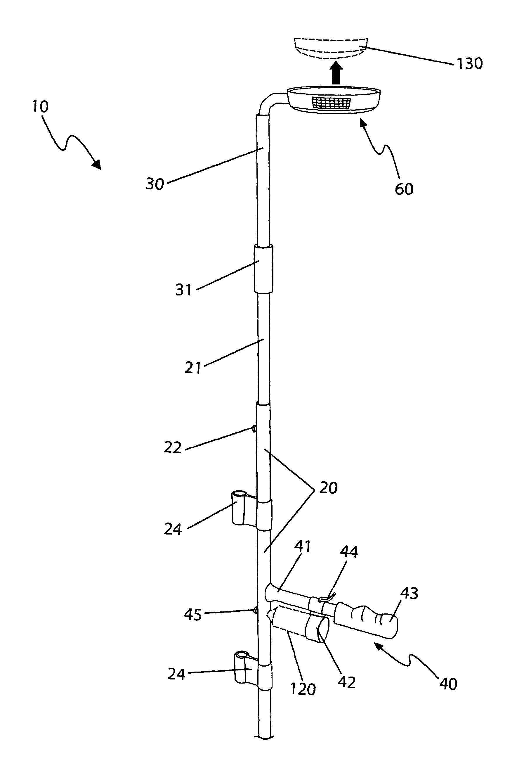
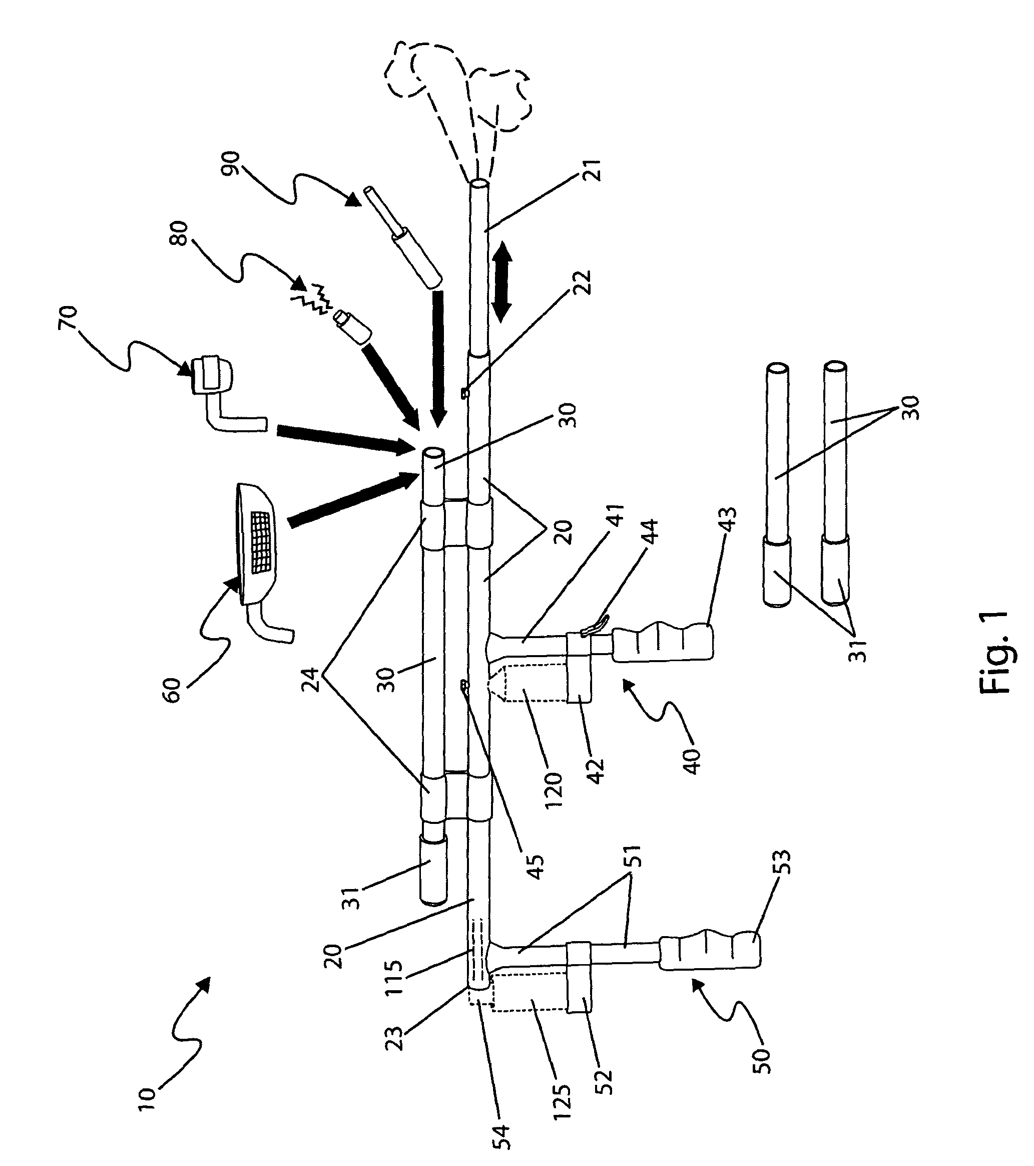
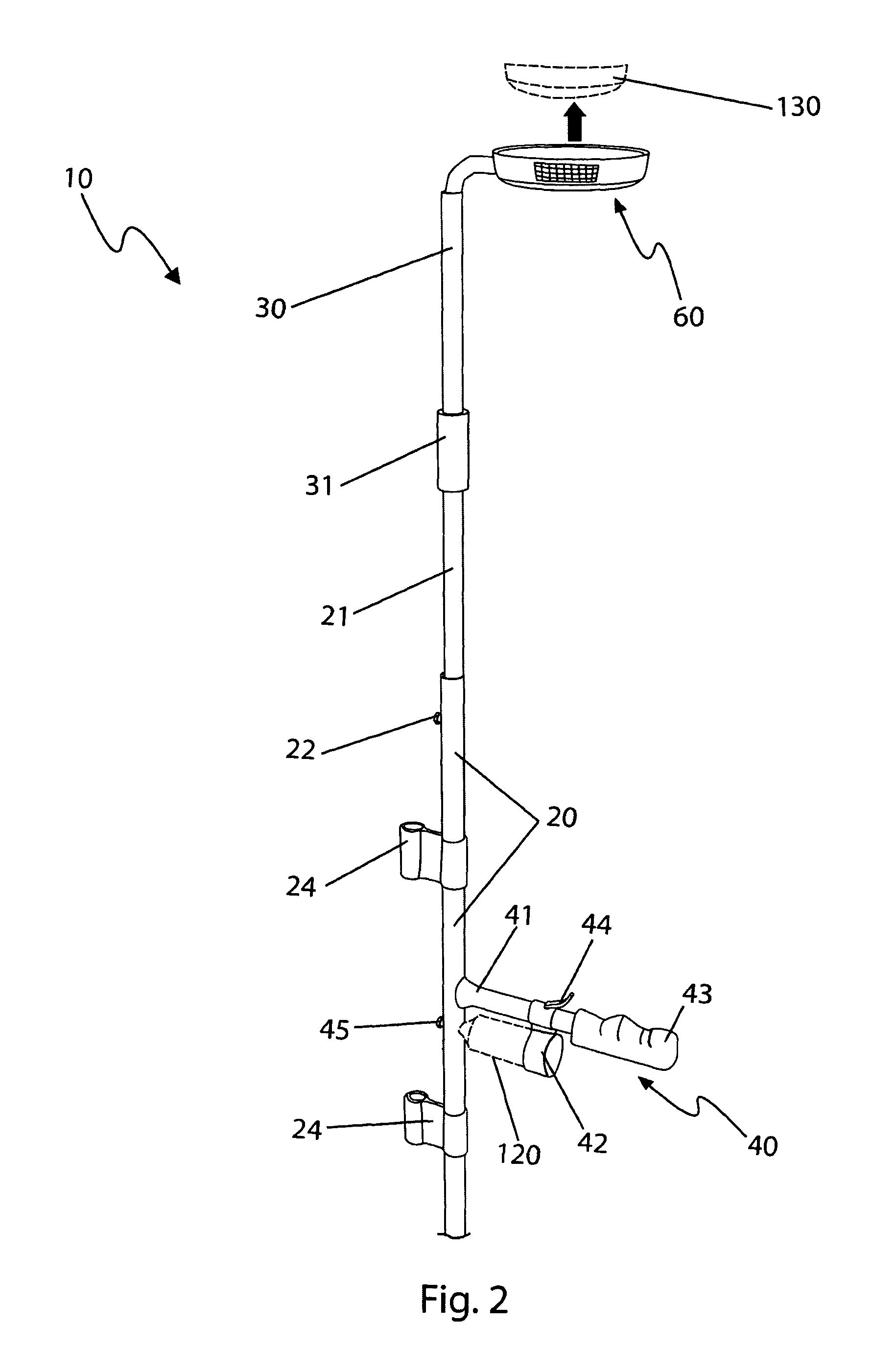
[0044]The best mode for carrying out the invention is presented in terms of its preferred embodiment, herein depicted within FIGS. 1 through 4. However, the invention is not limited to the described embodiment and a person skilled in the art will appreciate that many other embodiments of the invention are possible without deviating from the basic concept of the invention, and that any such work around will also fall under scope of this invention. It is envisioned that other styles and configurations of the present invention can be easily incorporated into the teachings of the present invention, and only one particular configuration shall be shown and described for purposes of clarity and disclosure and not by way of limitation of scope.

[0045]The terms “a” and “an” herein do not denote a limitation of quantity, but rather denote the presence of at least one of the referenced items.

[0046]The present invention describes a smoke detector testing tool (herein described as the “apparatus”...


PUM


Abstract

An apparatus to aid in the testing of smoke detectors comprises a rifle-shaped design which holds and dispenses aerosol cans of smoke and air is herein disclosed. The apparatus is approximately four (4) feet long and includes additional extension tubes approximately three (3) feet long. In such a manner the apparatus is capable of reaching smoke detectors that are seven (7) feet or more above the users head. In addition to dispensing smoke for testing and air for purging, the apparatus also includes a magnetic adapter for testing smoke detector switches, a mechanical probe attachment for smoke detector activation, and a holder for electronic devices such as barcode scanners. In such a manner the testing and maintenance of most smoke detectors can be performed safely from ground level without the use of ladders or other assistance.

Description

RELATED APPLICATIONS[0001]The present invention was first described in a notarized Official Record of Invention on Apr. 3, 2008, that is on file at the offices of Montgomery Patent and Design, LLC, the entire disclosures of which are incorporated herein by reference.FIELD OF THE INVENTION[0002]The present invention relates generally to an apparatus to aid in the testing of smoke detectors and, more particularly, to said apparatus comprising a rifle-shaped design which holds and dispenses aerosol containers of smoke and air for enabling a user to position said containers close to test said smoke detectors.BACKGROUND OF THE INVENTION[0003]Perhaps the most important device present in a home to protect lives and property is the smoke alarm detector. These devices provide an excellent means of detecting the early stages of fire thus giving occupants adequate time to escape. However, for such devices to work effectively they must be tested. While just about all units provide a test button...

Claims


Application Information

Patent Timeline
IPC IPC(8): G08B29/12
CPCG08B29/145
Inventor HALLISEY, RICHARD D.
Owner HALLISEY RICHARD D
Learn More