Pressure sensor for measurements in a chamber of an internal combustion engine

a technology of pressure sensor and internal combustion engine, which is applied in the direction of combustion process, combustion ignition, lighting and heating apparatus, etc., can solve the problems of pressure elements, glow plugs, and can only be operated with the required accuracy with great effor

Inactive Publication Date: 2012-06-26
KISTLER HLDG AG
View PDF24 Cites 17 Cited by
  • Summary
  • Abstract
  • Description
  • Claims
  • Application Information

AI Technical Summary

Benefits of technology

[0014]The object of the present invention is to specify a pressure-measuring element of the type mentioned at the start which has fewer sources of error caused by force transmission.
[0016]The idea on which the invention is based consists in the pressure element being supported on the measuring element by means of the diaphragm. The pressure element is thus arranged at a distance from the measuring element. This means it is no longer necessary to create a very precisely defined contact face between the pressure element and the measuring element.

Problems solved by technology

This is therefore important because some pressure elements, such as in particular that of a glowplug, can only be operated with the required accuracy with great effort.

Method used


Image

  • Pressure sensor for measurements in a chamber of an internal combustion engine
  • Pressure sensor for measurements in a chamber of an internal combustion engine
  • Pressure sensor for measurements in a chamber of an internal combustion engine

Examples


Embodiment Construction

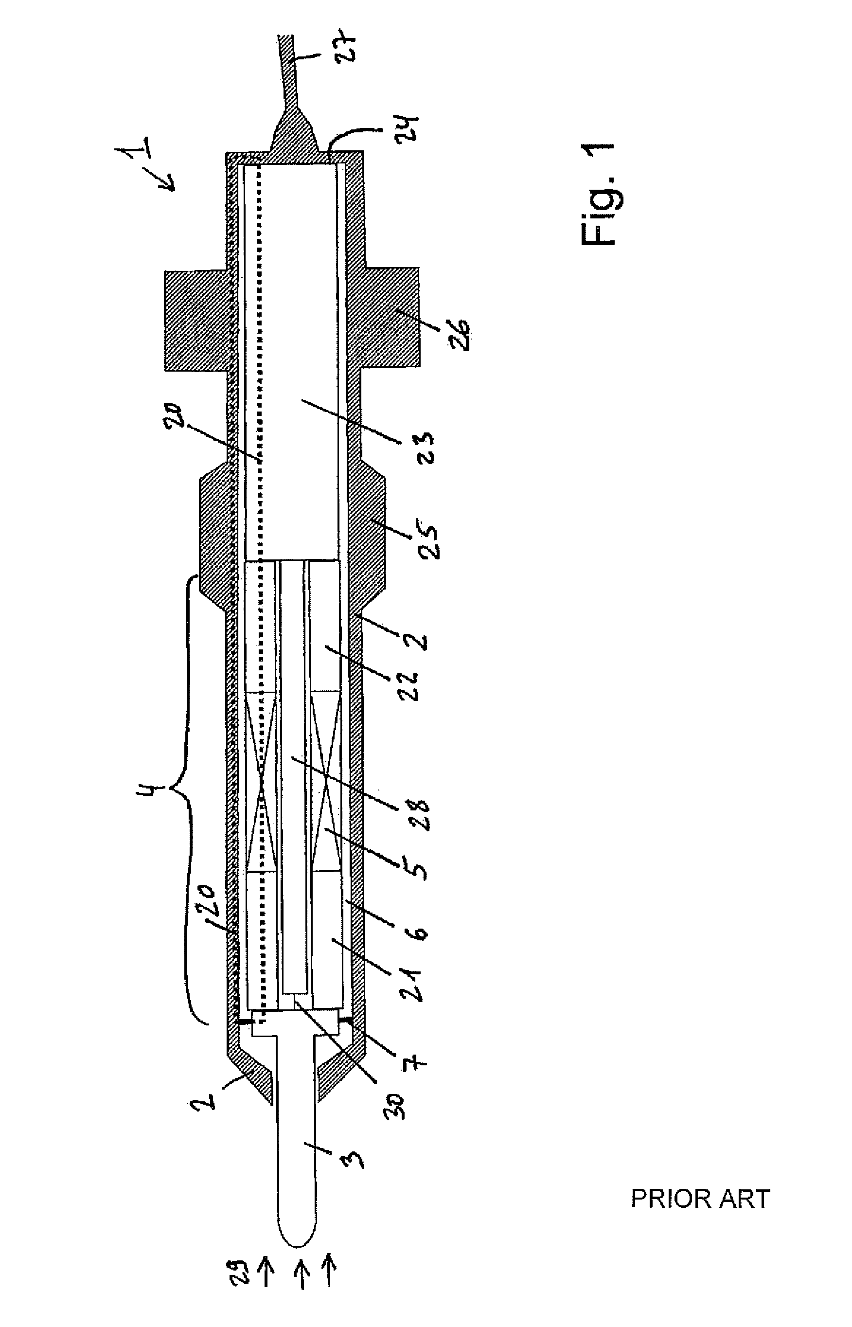
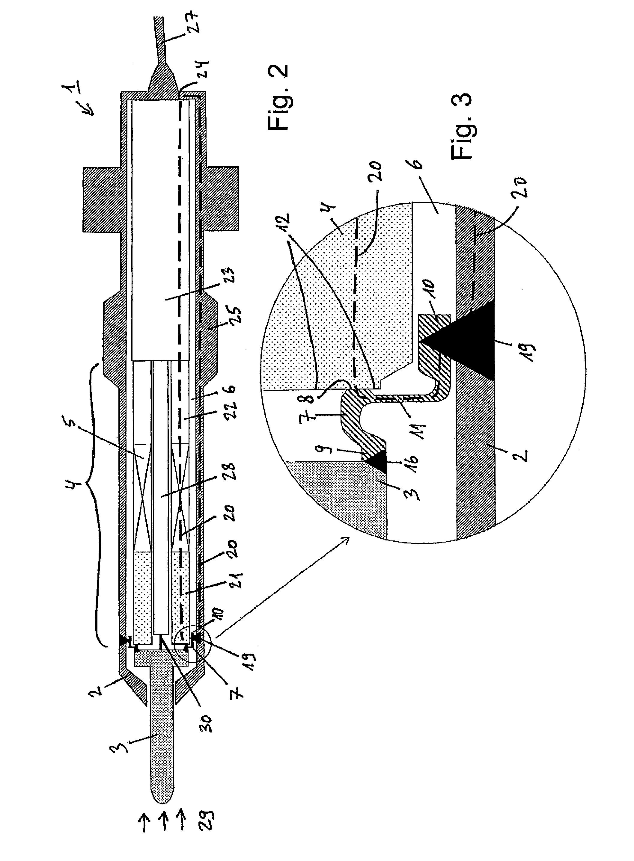
[0026]FIG. 2 shows a configuration according to the invention of a pressure sensor 1 for measurements in a chamber 29 of an internal combustion engine in a preferred embodiment. This illustration likewise comprises a housing 2 and a pressure element 3 which in this case projects out of the housing 2. A measuring element 4 is arranged in the housing 2 downstream of this pressure element 3 in the pressure direction. This measuring element comprises a force transmission element 21, adjacently to this in the pressure direction a sensor element 5 and adjacently to this in the pressure direction a fixing element 22. This fixing element 22 can, as in the prior art, be supported on further components of the pressure sensor 1, such as in this case on the connection element 23 and finally on the shoulder 24 of the housing 2. The force path 20 is indicated in FIG. 2 with dashed lines. It runs via the diaphragm 7 and in particular not via the pressure element 3.

[0027]This pressure element 1 is ...


PUM


Abstract

A pressure sensor for measurements in a chamber of an internal combustion engine, in particular a pressure-measuring glowplug, comprises a housing, a pressure element for picking up a pressure, and a measuring element arranged in the housing downstream of the pressure element in the direction of the pressure and having a sensor element and a diaphragm. This diaphragm is permanently connected at its first end to the pressure element, and at its second end it is directly or indirectly permanently connected to the housing at a connection, with the pressure element being supported on the measuring element via the diaphragm.

Description

CROSS-REFERENCE TO RELATED APPLICATIONS[0001]This application claims priority to International Application Serial No. PCT / CH2009 / 000154 filed May 12, 2009, which claims priority to Swiss Application No. CH 856 / 08 filed Jun. 4, 2008.TECHNICAL FIELD[0002]The invention relates to a pressure sensor for measurements in a chamber of an internal combustion engine, in particular a pressure-measuring glowplug, comprising a housing, a pressure element for picking up a pressure, and a measuring element arranged in the housing downstream of the pressure element in the pressure direction and having a sensor element and a diaphragm which is permanently connected at its first end to the pressure element and is permanently directly or indirectly connected at its second end to the housing.BACKGROUND[0003]Similar pressure sensors to that mentioned at the start are known for example from WO 2006 / 089446. In this pressure sensor, a diaphragm is situated in the front region of the glowplug, which diaphra...

Claims


Application Information

Patent Timeline
Patent Type & Authority Patents(United States)
IPC IPC(8): G01M15/08
CPCG01L23/10G01L23/222F23Q2007/002F23Q7/001
Inventor MUELLER, MICHAEL
Owner KISTLER HLDG AG
Why Eureka
Try Eureka