Eureka AIR delivers breakthrough ideas for toughest innovation challenges, trusted by R&D personnel around the world.

Method and apparatus for distributing signals

a technology of signal distribution and signal equipment, applied in the field of signal distribution techniques, can solve the problems of significant impairing the quality of service provided to end users, service providers can expect to encounter problems with multimedia content distribution over existing coaxial home wiring, and end users

Active Publication Date: 2012-06-26
SBC KNOWLEDGE VENTURES LP
View PDF9 Cites 1 Cited by
  • Summary
  • Abstract
  • Description
  • Claims
  • Application Information

AI Technical Summary

Problems solved by technology

As broadband communications such as fiber and / or very high bit rate digital subscriber line (VDSL), and / or cable modem signals are distributed to residences and commercial enterprises, service providers can expect to encounter issues with multimedia content distribution over existing coaxial home wiring.
Such high losses can significantly impair the quality of service provided to end users.
With such assistance, it may occur to the end user that too many splitters have been placed in series between the affected devices, a coaxial cable has been damaged, or the coaxial cable connecting the devices has been inadvertently disconnected.

Method used


Image

  • Method and apparatus for distributing signals
  • Method and apparatus for distributing signals
  • Method and apparatus for distributing signals

Examples


first embodiment

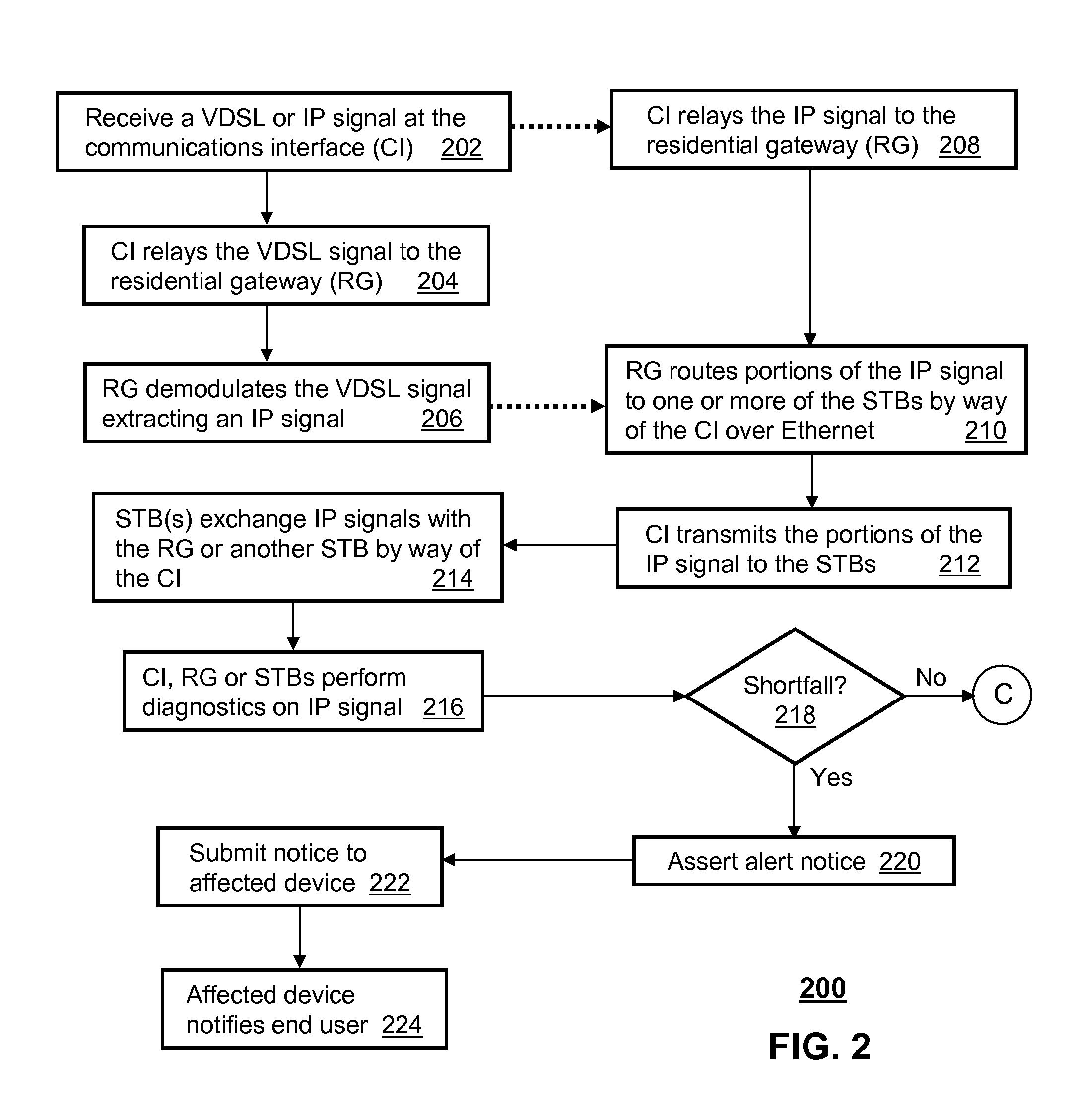
[0009]In the present disclosure, a communications interface (CI) can have a controller that manages a transceiver coupled to a residential gateway (RG) and one or more set top boxes (STBs). The controller can be programmed to receive a very high bit rate digital subscriber line (VDSL) signal, transmit the VDSL signal to the RG over a select one of a plurality of coaxial interfaces, and receive an IP signal from the RG for distribution to the one or more STBs.

second embodiment

[0010]In the present disclosure, a communications interface (CI) can have a controller that manages a transceiver coupled to a residential gateway (RG) and one or more set top boxes (STBs). The controller can be programmed to receive a first flow of IP packets from an optical signal, transmit the first flow of IP packets to the RG over a select one of a plurality of coaxial interfaces, and receive a second flow of IP packets from the RG for distribution to the one or more STBs.

third embodiment

[0011]In the present disclosure, a computer-readable storage medium in a residential gateway (RG) can have computer instructions for receiving a very high bit rate digital subscriber line (VDSL) signal from a communications interface (CI) over a coaxial interface, demodulating the VDSL signal into IP constructs, and routing portions of the IP constructs to one or more set top boxes (STBs) by way of the CI according to an Ethernet protocol managed in part by the CI.

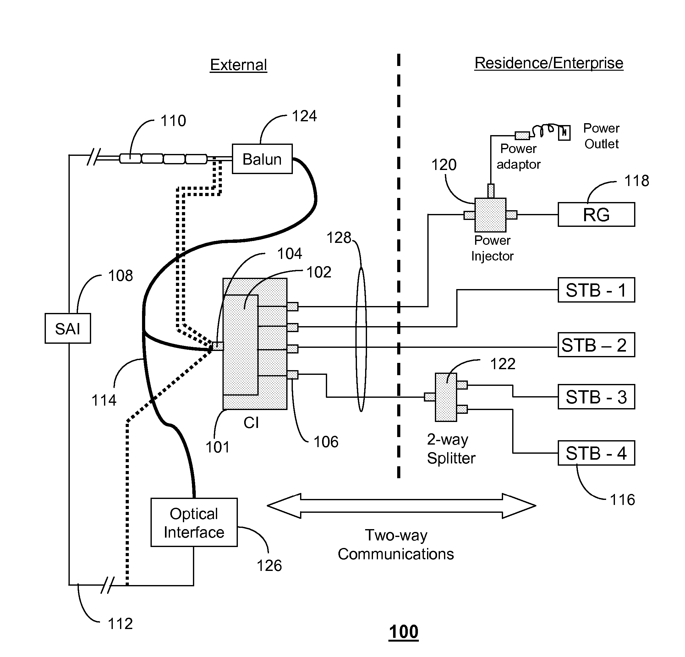
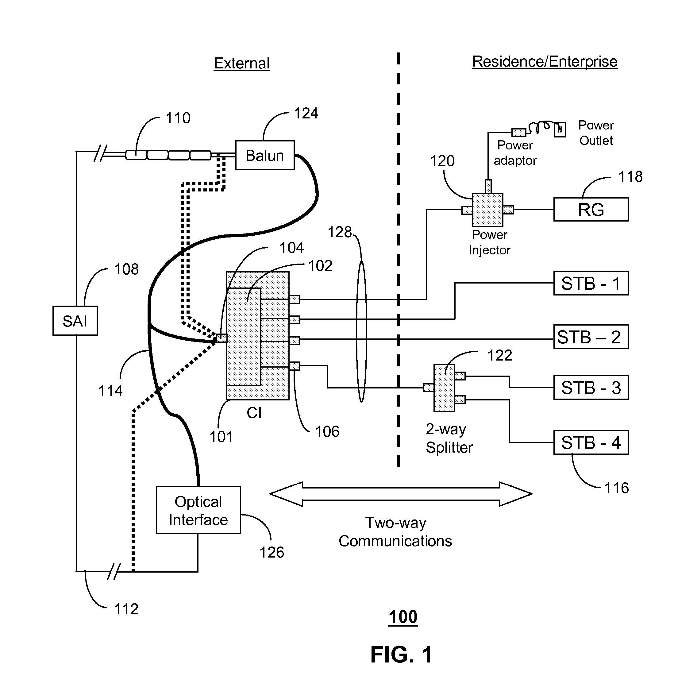
[0012]FIG. 1 depicts an exemplary embodiment of a signal distribution system (SDS) 100. The SDS 100 comprises a communications interface (CI) 101 coupled to a residential gateway (RG) 118 and a number of set top boxes (STBs) 116. The STBs 116 can represent a common digital video recorder (DVR) processor, a standard definition TV (SDTV) processor, a high definition TV (HDTV) processor, and combinations thereof. The RG 118 can comprise a common modem for modulating and demodulating signals exchanged with another high speed m...


PUM


Abstract

A system and method are disclosed for method and apparatus for distributing signals. A system that incorporates teachings of the present disclosure may include, for example, a communications interface (CI) (101 having a controller that manages a transceiver (102) coupled to a residential gateway (RG) (118) and one or more set top boxes (STBs) (116). The controller can be programmed to receive (202) a very high bit rate digital subscriber line (VDSL) signal, transmit (204, 208) the VDSL signal to the RG over a select one of a plurality of coaxial interfaces, and receive (210) an IP signal from the RG for distribution to the one or more STBs. Additional embodiments are disclosed.

Description

FIELD OF THE DISCLOSURE[0001]The present disclosure relates generally to signal distribution techniques, and more specifically to a method and apparatus for distributing signals.BACKGROUND[0002]As broadband communications such as fiber and / or very high bit rate digital subscriber line (VDSL), and / or cable modem signals are distributed to residences and commercial enterprises, service providers can expect to encounter issues with multimedia content distribution over existing coaxial home wiring. In systems involving two-way communications between a residential gateway (RG) and set top boxes (STBs) and between STBs themselves, it is likely that end users will utilize common RF coaxial splitters at various points within the coaxial network in most instances without notice to the service provider.[0003]Generally, a two-way coaxial splitter will incur a loss of 3.5 dB when transmitting a signal from input to output or vice-versa. Such losses are acceptable so long as only a few splitters...

Claims


Application Information

Patent Timeline
Patent Type & Authority Patents(United States)
IPC IPC(8): H04N7/18
CPCH04N7/106H04N7/17309H04N21/43615H04N21/43622H04N21/6125
Inventor ANSARI, AHMADREED, VERNONCOSTA, PIERREHARTMAN, DAVID
Owner SBC KNOWLEDGE VENTURES LP
Why Eureka
Eureka Blog
Learn More