Data capture terminal with automatic focusing over a limited range of working distances
What is Al technical title?
Al technical title is built by PatSnap Al team. It summarizes the technical point description of the patent document.
a data capture terminal and working distance technology, applied in the field of data capture terminals with automatic focusing over a, can solve the problems of vibration generation, disadvantage of automatic focusing, wear of parts,
Active Publication Date: 2012-07-03
SYMBOL TECH LLC
View PDF9 Cites 0 Cited by
Summary
Abstract
Description
Claims
Application Information
AI Technical Summary
This helps you quickly interpret patents by identifying the three key elements:
Problems solved by technology
Method used
Benefits of technology
[0014]Thus, rather than having the controller attempt to capture the data and analyze the captured data in each different optical position, or at each different voltage, throughout the entire extended range of working distances to see if a successful data capture has indeed occurred, one aspect of this invention proposes that such data capture and analysis only occur in a smaller subset of optical positions or voltages, thereby enhancing data capture performance of the terminal. The smaller subset contains the stored position or voltage of the last successful data capture. This invention assumes that the next target will be approximately at or near the same working distance as the last successfully processed target.
[0016]Another aspect of the invention resides in a method of automatically capturing data from targets located within a range of working distances from a data capture terminal. The method is performed by focusing and capturing return light from the targets over a field of view of an imaging assembly, generating respective electrical signals each indicative of the captured return light, processing one of the electrical signals from one of the targets into data indicative of the one target by automatically controlling a set of focal parameters of the imaging assembly, determining that the data of the one target has been successfully captured, storing one of the focal parameters of the imaging assembly upon a successful determination, configuring the set of focal parameters of the imaging assembly to correspond to the range of working distances, subsequently processing another of the electrical signals from another of the targets into data indicative of the other target by automatically selecting a subset of the focal parameters determined by the stored one focal parameter, determining that the data of the other target has been successfully captured, containing the stored one focal parameter in the subset, configuring the subset to be smaller than the set of the focal parameters of the imaging assembly, and configuring the subset to correspond to a restricted zone within the range of working distances to enhance data capture performance of the terminal.
Problems solved by technology
However, such automatic focusing is disadvantageous for several reasons.
First, the mechanical movement generates vibrations that are propagated through the terminal to an operator's hand in a handheld mode of operation, and may also generate dust to obscure the imaging lens assembly lens assembly, and may cause parts to wear out over time.
Moreover, the vibrations can generate objectionable, annoying, audible hum.
In addition, the mechanical lens movement requires a drive that, in turn, consumes electrical power, is expensive and slow, can be unreliable, occupies space and increases the overall weight, size and complexity of the terminal.
Also, the rangefinder itself represents added expense, size and complexity.
Although the known automatic focusing data capture terminals are generally satisfactory for their intended purpose, the focusing adjustment performed over a multitude of optical positions typically takes too long.
Method used
Image
Click on the blue label to locate the original text in one second.
Reading with bidirectional positioning of images and text.
Examples
Embodiment Construction
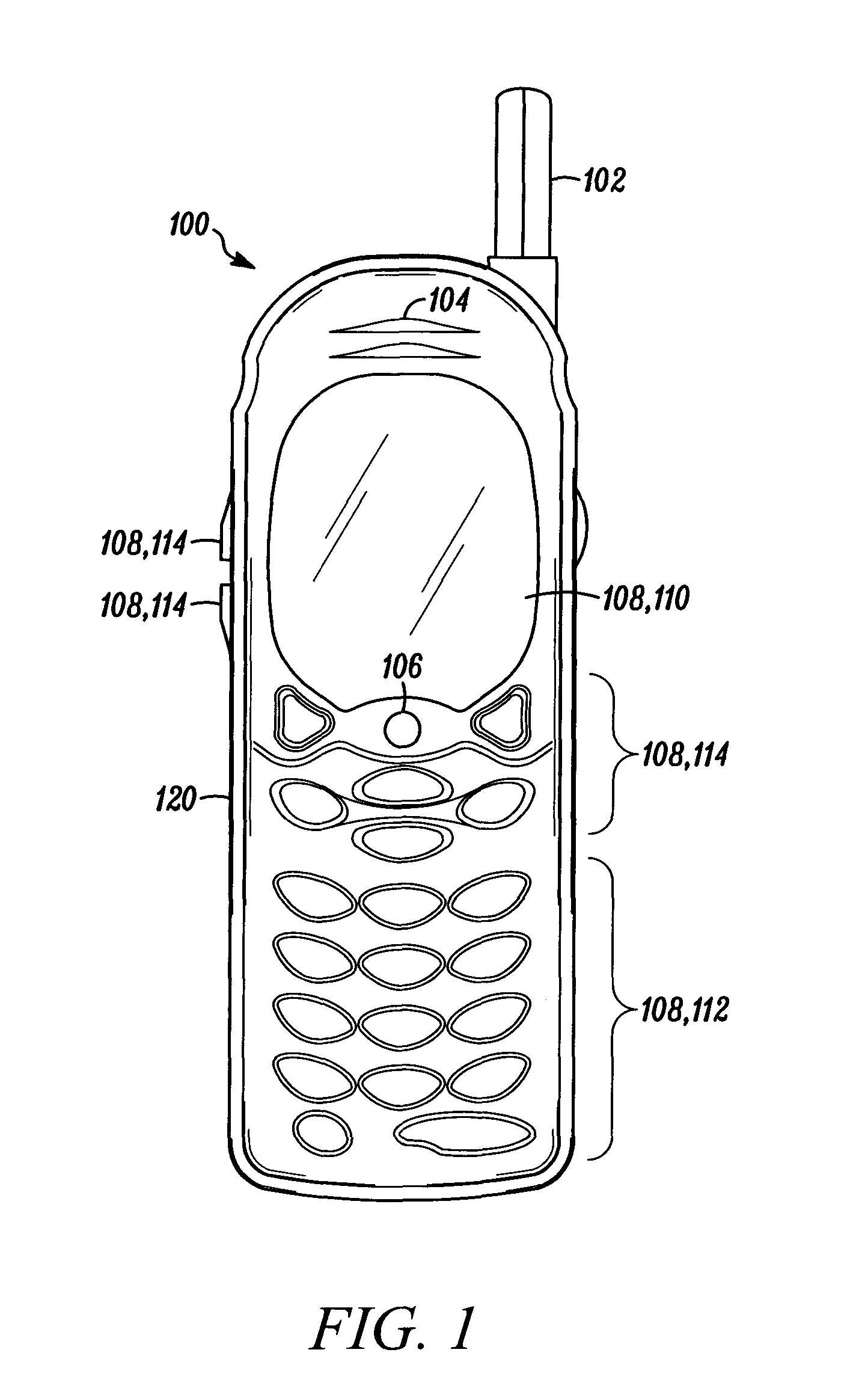
[0024]A portable data capture terminal for, and a method of, automatically capturing data from targets, such as bar code symbols and non-symbol targets, according to the present invention, is generally shown in FIG. 1 as a radiotelephone 100, such as a cellular telephone operable in a cellular telephone system. Although a radiotelephone 100 is shown in FIG. 1, one skilled in the art will recognize that the features discussed hereinbelow will also find application in other mobile computers, such as smartphones, personal digital assistants (PDAs), audio and / or video players, portable gaming systems, radios, video cameras, scanners, pagers, video telephones, handheld computers, and other microprocessor-controlled electronic devices, especially those having network access, and the radiotelephone 100 or data capture terminal described herein shall refer to each of these and their equivalents.
[0025]As shown in FIG. 1, the radiotelephone 100 includes a housing 120, a radio frequency (RF) a...
PUM
Abstract
A data capture terminal for, and a method of, automatically capturing data from targets located within a range of working distances from the terminal, employ a controller for automatically controlling a set of focal parameters of an imaging assembly, for storing one of the focal parameters of the imaging assembly upon a successful data capture from a first target, and for automatically selecting a subset of the focal parameters determined from the stored focal parameter to capture data from a second target. The subset is smaller than the set of the focal parameters and corresponds to a restricted zone within the range of working distances to enhance data capture performance of the terminal.
Description
DESCRIPTION OF THE RELATED ART[0001]Portable terminals equipped with solid-state imaging systems, in both handheld and hands-free modes of operation, have been used in many applications, such as supermarkets, warehouse clubs, department stores, and other kinds of retailers, as well as package delivery systems, for many years, to electro-optically capture data from various targets, by reading indicia, such as one-dimensional bar code symbols, particularly of the Universal Product Code (UPC) type, each having a row of bars and spaces spaced apart along a scan direction, and by reading two-dimensional symbols, such as Code 49, which introduced the concept of vertically stacking a plurality of rows of bar and space patterns in a single symbol as described in U.S. Pat. No. 4,794,239, as well as by capturing images of non-symbol targets, such as persons, places, or things. For example, the image of a consumer, or the consumer's signature, or the consumer's driver's license might be captur...
Claims
Application Information
Patent Timeline
Application Date:The date an application was filed.
Publication Date:The date a patent or application was officially published.
First Publication Date:The earliest publication date of a patent with the same application number.
Issue Date:Publication date of the patent grant document.
PCT Entry Date:The Entry date of PCT National Phase.
Estimated Expiry Date:The statutory expiry date of a patent right according to the Patent Law, and it is the longest term of protection that the patent right can achieve without the termination of the patent right due to other reasons(Term extension factor has been taken into account ).
Invalid Date:Actual expiry date is based on effective date or publication date of legal transaction data of invalid patent.