Engineered push up insert

a push-up insert and insert technology, applied in the field of push-up inserts, can solve the problems of prior art pads not anatomically fitting the breasts, and achieve the effect of natural shape, increased volume and cleavag

Active Publication Date: 2012-07-10
RUNBERG INC
View PDF9 Cites 15 Cited by
  • Summary
  • Abstract
  • Description
  • Claims
  • Application Information

AI Technical Summary

Benefits of technology

[0005]There exists a need for a soft shaping insert that is anatomically designed to conform to and push up the breasts, thereby increasing volume and cleavage, while providing a natural shape.

Problems solved by technology

The prior art foam pads do not push up breasts and do not create cleavage and volume.
The prior art pads do not anatomically fit the breasts to provide natural-looking, enhanced cleavage.

Method used


Image

  • Engineered push up insert
  • Engineered push up insert
  • Engineered push up insert

Examples


Embodiment Construction

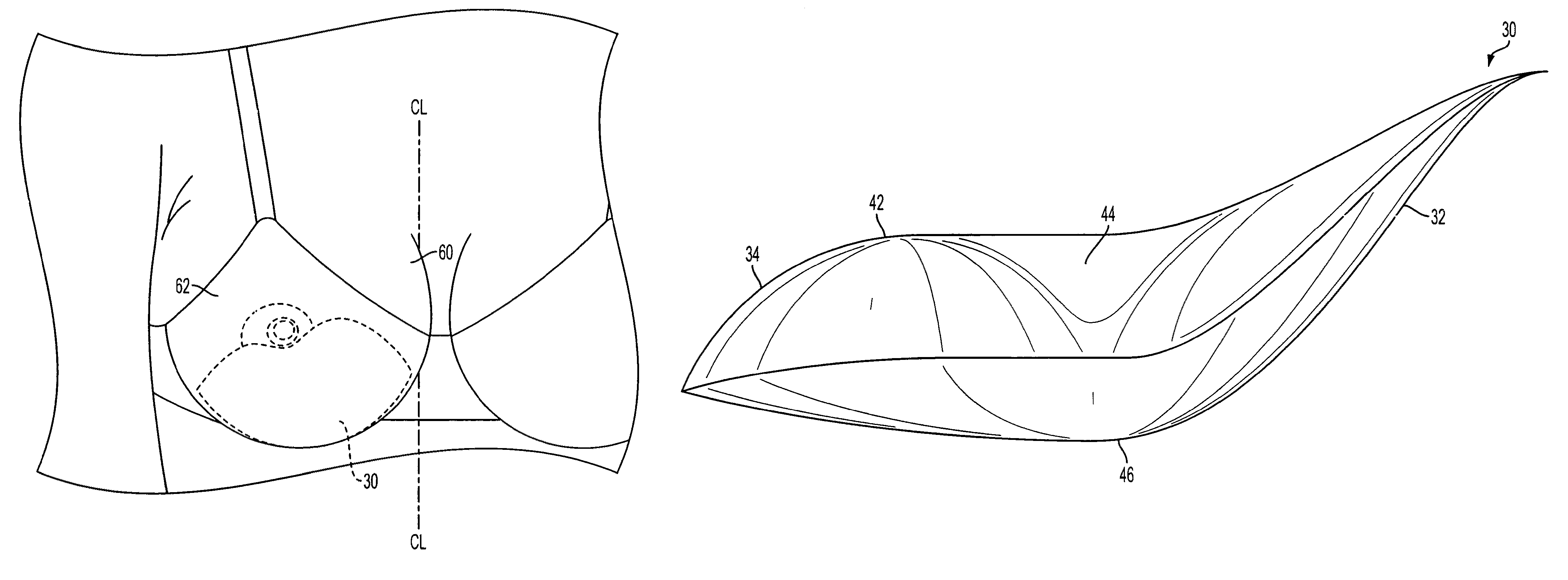
[0030]According to an embodiment of the present disclosure, a kidney-shaped push up insert 30 is provided comprising a first lobe 32, and a second lobe 34 on an opposing side of the insert 30 from the first lobe 32, as shown in FIG. 3. The insert 30 has a top side 36, and a bottom side 38 on an opposing side of the insert 30 from the top side 36. A notch 40 is formed in the top side 36 between the first lobe 32 and second lobe 34. The insert 30 has a first main surface 42 having a depression 44 formed adjacent the top side 36 and the depression 44 extends towards the notch 40, as shown in FIGS. 4 and 5. A second main surface 46 opposes the first main surface 42. The second main surface 46 is a substantially smooth arcuate-shaped surface. The first lobe 32 is narrower in width between the top side 36 and the bottom side 38 than the second lobe 34, and the second lobe 34 is thicker between the first main surface 42 and the second main surface 46 than the first lobe 32. A ratio of a ma...


PUM


Abstract

Kidney-shaped push up insert including first lobe and second lobe is provided. Notch is formed in top side between first lobe and second lobe. Insert has depression formed adjacent top side extending towards notch. Second main surface opposes first main surface. Second main surface is substantially smooth arcuate-shaped surface. First lobe has narrower width between top side and bottom side than second lobe, and second lobe is thicker between first main surface and second main surface than first lobe. Ratio of maximum thickness between first main surface and second main surface to maximum length between opposing ends of first lobe and second lobe is less than about 9 and/or ratio of depth of notch from a straight line connecting first lobe and second lobe along top side of insert to width of insert from top side to bottom side at depth of notch is less than about 4.

Description

RELATED APPLICATION[0001]This application claims the benefit of priority of U.S. Provisional Application Ser. No. 61 / 085,335 filed Jul. 31, 2008.FIELD OF THE INVENTION[0002]The present disclosure is directed to push up inserts for enhancing cleavage and adding volume, thus, improving appearance and the fit of clothing.BACKGROUND[0003]Pads are typically inserted into the cups of a bra to fill out the bra. An example of a plastic pad is shown in FIG. 1, illustrating an approximately semi-circular-shaped pad 10. FIG. 2 illustrates another example of a pad 20 having cloth exterior encasing a foam pad. The cloth / foam pad is thin, about ½ inch thick at its maximum thickness. The outer cloth exterior of the foam pad 20 is secured by stitching 22 around the periphery 24 of the pad 20.[0004]The prior art foam pads do not push up breasts and do not create cleavage and volume. The prior art plastic and foam pads do not wrap around breasts and are not contoured to the breast to create a natural...

Claims


Application Information

Patent Timeline
Patent Type & Authority Patents(United States)
IPC IPC(8): A41C3/00
CPCA41C3/144A41C3/10
Inventor MACKINNON, DEBRA
Owner RUNBERG INC
Why Eureka
Try Eureka