Adjustment of radiation patterns utilizing a position sensor

a position sensor and radiation pattern technology, applied in the field of wireless communication, can solve problems such as changes or disturbances, wireless links, and other radio transmitting devices, and achieve the effect of reducing the risk of interference, and reducing the service li

Active Publication Date: 2012-07-10
ARRIS ENTERPRISES LLC
View PDF244 Cites 50 Cited by
  • Summary
  • Abstract
  • Description
  • Claims
  • Application Information

AI Technical Summary

Problems solved by technology

A wireless link in an Institute of Electrical and Electronic Engineers (IEEE) 802.11 network may be susceptible to interference from other access points and stations, other radio transmitting devices, and changes or disturbances in the wireless link environment between an access point and remote receiving node.
The interference may degrade the wireless link thereby forcing communication at a lower data rate.
The interference may, in some instances, be sufficiently strong as to disrupt the wireless link altogether.
Many methods that provide for switching among antenna configurations, such as diversity antennas, and other methods of controlling antenna segments fail to effectively minimize the interference from other access points, other radio transmitting devices, or disturbances in the environment of the wireless link between the access point and the remote receiving node.
The trial-and-error approach is inefficient as it generally requires transmission on a “bad” antenna configuration to determine the particularities of the poor quality of that antenna configuration.
Further, as the transmitting or receiving device move around, new sources of interference arise to degrade a transmission.
The trial-and-error approach therefore becomes increasingly inefficient with a large number of antenna configurations and devices that may have adjustable positions.
The particulars of any given radiation pattern generated by a wireless device may be not be immediately apparent to an individual charged with creating a wireless network but otherwise lacking extensive knowledge into RF emission patterns.
Further difficulties might arise with respect to intermediate arrangements of the wireless device (e.g., at a 45 degree angle).
The problems associated with radiation patterns become even more apparent with respect to mobile devices, especially cellular phones or mobile devices with WiFi capability.

Method used


Image

  • Adjustment of radiation patterns utilizing a position sensor
  • Adjustment of radiation patterns utilizing a position sensor
  • Adjustment of radiation patterns utilizing a position sensor

Examples


Embodiment Construction

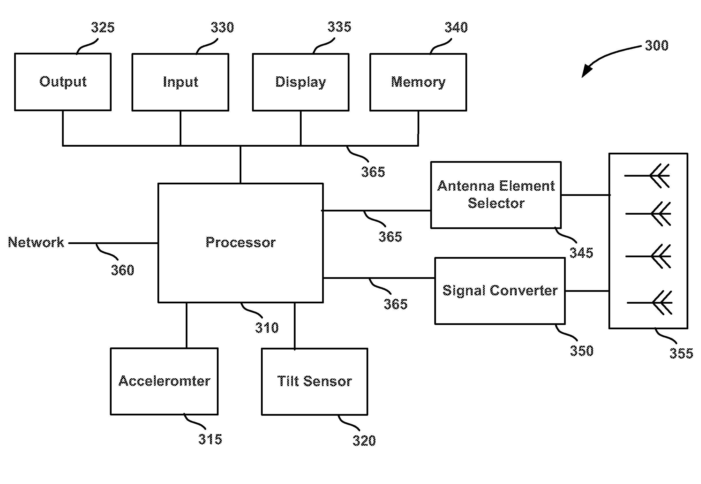
[0026]A device for a wireless RF link to a remote receiving device includes an antenna apparatus with selectable antenna elements for transmitting and receiving an RF signal, a signal converter for converting between encoded signals and RF signals, a processor for controlling the signal converter and the antenna apparatus, and a position sensor. As the device is moved, displaced, or re-positioned, the position sensor detects a change in position and provides position information to the processor. The processor receives the position information from the position sensor, selects an antenna configuration based on the position information, and selects a physical data rate to maximize data transmission speed. The processor then provides an encoded signal to the signal converter and controls the converter and antenna apparatus to provide an RF signal through the antenna elements of the selected antenna configuration.

[0027]For example, when the device is in a first position in a vertical a...


PUM


Abstract

A device for a wireless RF link to a remote receiving device can radiate at different radiation patterns in response to detecting a change in the device position. As the device is moved, displaced, or re-positioned, a position sensor in the device detects the change in position and provides position information to a processor. The processor receives the position information from the position sensor, selects an antenna configuration and physical data rate based on the position information, and provides an RF signal associated with the selected antenna configuration through the antenna elements of the selected antenna configuration.

Description

BACKGROUND OF THE INVENTION[0001]1. Field of the Invention[0002]The present invention generally relates to wireless communications and more particularly to changing radio frequency (RF) emission patterns with respect to one or more antenna arrays.[0003]2. Description of the Related Art[0004]In wireless communications systems, there is an ever-increasing demand for higher data throughput and a corresponding drive to reduce interference that can disrupt data communications. A wireless link in an Institute of Electrical and Electronic Engineers (IEEE) 802.11 network may be susceptible to interference from other access points and stations, other radio transmitting devices, and changes or disturbances in the wireless link environment between an access point and remote receiving node. The interference may degrade the wireless link thereby forcing communication at a lower data rate. The interference may, in some instances, be sufficiently strong as to disrupt the wireless link altogether.[...

Claims


Application Information

Patent Timeline
Patent Type & Authority Patents(United States)
IPC IPC(8): H01Q1/24
CPCH01Q1/2291H01Q3/24H04B7/063H04L1/20H04L1/0002H04W84/12H04W24/02H04W72/0413H04B7/0619H04W72/21
Inventor SHTROM, VICTORBARON, BERNARDKISH, WILLIAM S.
Owner ARRIS ENTERPRISES LLC
Why Eureka
Try Eureka