Integrated vibration measurement and analysis system

a vibration measurement and analysis system technology, applied in the field of machine vibration measurement, can solve problems such as mechanical imbalance, broken rotor bars, and gear tooth breakage, and achieve the effect of reducing hardware complexity and data storage requirements

Active Publication Date: 2014-03-06
COMPUTATIONAL SYST
View PDF10 Cites 198 Cited by
  • Summary
  • Abstract
  • Description
  • Claims
  • Application Information

AI Technical Summary

Benefits of technology

[0055]The above and other needs are met by a vibration data collection system that performs the integration or differentiation process on incoming digitized vibration data in real time. The system uses digital Infinite Impulse Response (IIR) filters running at the input data rate to provide the integration or differentiation function. With this approach, the system reduces hardware complexity and data storage requirements. Also, the system provides the ability to directly integrate or differentiate stored time waveforms without resorting to FFT processing methods.

Problems solved by technology

Some example fault conditions include mechanical imbalance, misalignment, bent shaft, soft foot, looseness, resonance, broken rotor bar, broken gear tooth, bearing defect, oil whirl, oil whip, phase imbalance, and turn-to-turn short circuit.

Method used


Image

  • Integrated vibration measurement and analysis system
  • Integrated vibration measurement and analysis system
  • Integrated vibration measurement and analysis system

Examples


Embodiment Construction

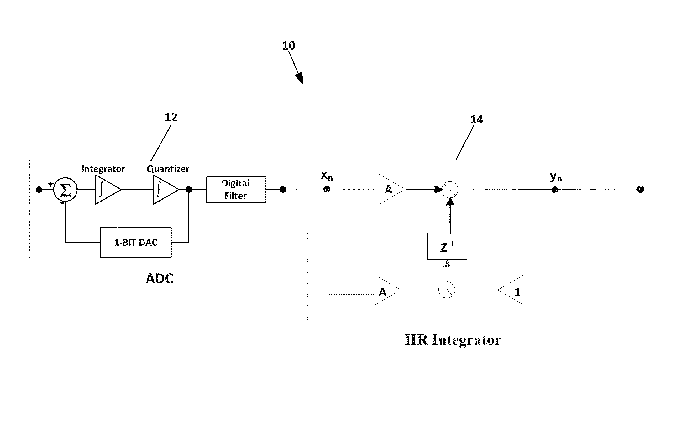
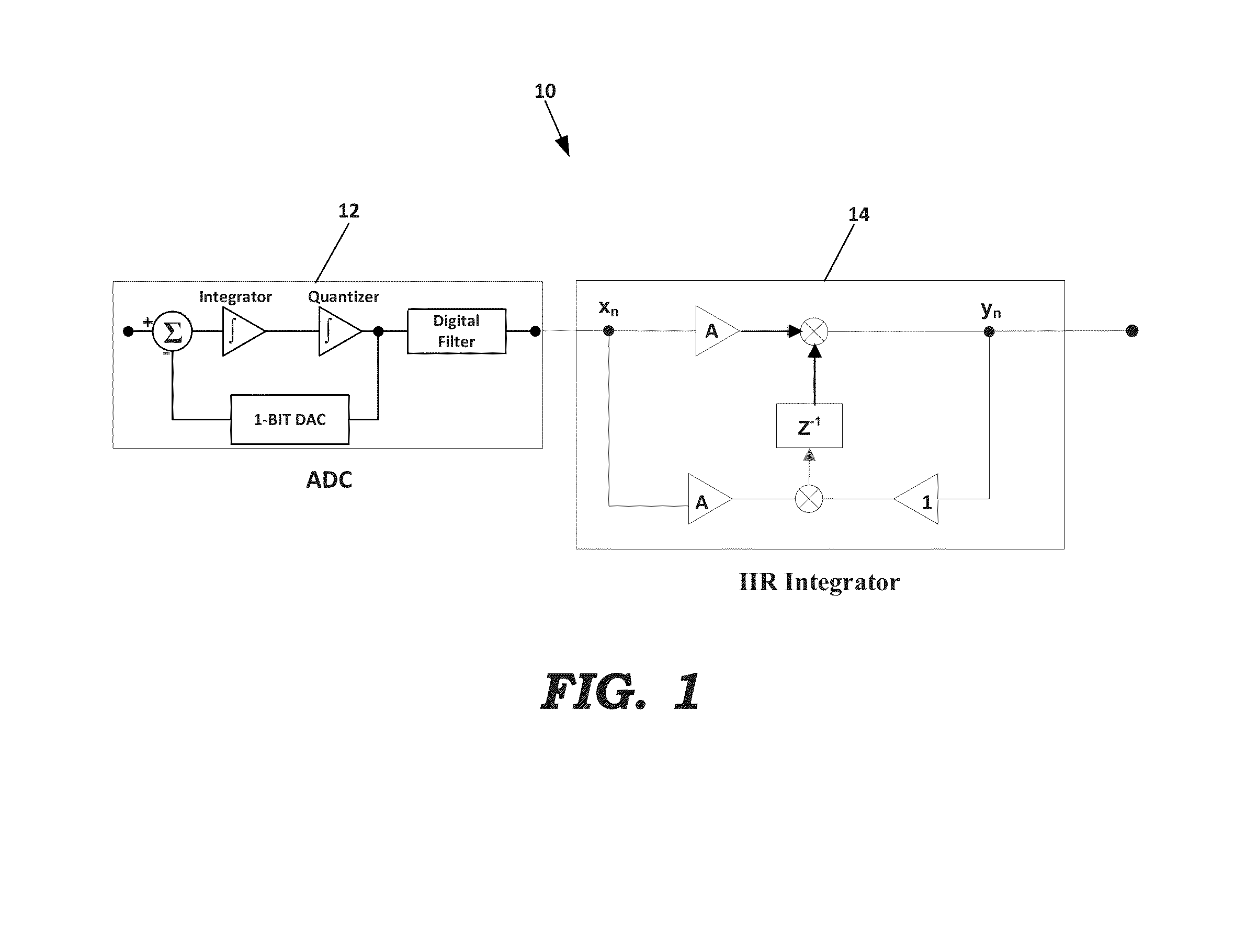
[0078]Real-Time Digital Integrator

[0079]The basic structure for an ideal real-time integrator system 10 is depicted in FIG. 1. The ideal system 10 includes an analog-to-digital converter (ADC) 12 and an ideal integrator 14. The ideal integrator 14 may be implemented using a difference equation which requires only one multiply operation, two addition operations and one storage location per ADC clock cycle. This difference equation is expressed as:

yn:=yn-1+A(xn+xn-1),   (1)

where yn is the current output value, xn is the current input value, yn-1 is the previous output value and xn-1 is the previous input value. In equation (1), A is a constant derived from the conversion factor.

[0080]The difference equation (1) may be derived by taking the ideal integrator transfer function in the s-domain (complex frequency domain) according to:

H(s):=As(2)

where

s:=2·(1-z-1)dt·(1+z-1).(3)

Applying the bilinear transform results in the following relationship:

X(Z)·X(1+Z-1):=Y(Z)·(1-Z-1)A(4)

Rearranging ter...


PUM


Abstract

A vibration data collection system performs an integration or differentiation process on incoming digitized vibration data in real time. The system uses a digital Infinite Impulse Response (IIR) filter running at the input data rate to provide the integration or differentiation function. With this approach, the system reduces hardware complexity and data storage requirements. Also, the system provides the ability to directly integrate or differentiate stored time waveforms without resorting to FFT processing methods.

Description

RELATED APPLICATIONS[0001]This application claims priority as a continuation of U.S. patent application Ser. No. 12 / 856,938 titled “Integrated Vibration Measurement and Analysis System” filed on Aug. 16, 2010.FIELD[0002]This invention relates to the field of machine vibration measurement for detecting mechanical, electrical, and electromagnetic fault conditions in an operating machine. More particularly, this invention relates to a system for performing real-time digital processing of time domain signals indicative of vibration produced by a machine.BACKGROUND[0003]Problems with Conventional Analog Integration in Machine Monitoring Systems[0004]Conversion from one type of vibration-related signal (such as acceleration) to another vibration-related signal (such as velocity or displacement) is a common requirement for vibration monitoring systems. A typical example is the conversion from acceleration to velocity by integration of the acceleration signal. Similarly, the opposite conver...

Claims


Application Information

Patent Timeline
Patent Type & Authority Applications(United States)
IPC IPC(8): G01H17/00
CPCG01H17/00G01H1/003G01N29/11G01N29/14G01N29/449G01N2291/011G01N2291/0258G01M99/005
Inventor BALDWIN, JOSEPH C.
Owner COMPUTATIONAL SYST
Why Eureka
Try Eureka