
Methods and systems for dual fuel injection

Active Publication Date: 2016-12-15
FORD GLOBAL TECH LLC
View PDF25 Cites 27 Cited by
  • Summary
  • Abstract
  • Description
  • Claims
  • Application Information

AI Technical Summary

Benefits of technology

The patent text describes a method for engines that use both direct and port fuel injection systems. The method involves using a high pressure fuel pump to supply fuel to both injection systems and controlling the timing of the port fuel injection to reduce fluctuations in the fuel rail pressure. This results in improved fuel metering and reduced emissions, while also eliminating the need for a dedicated fuel line for the port injection system. The technical effect of this method is improved engine performance and reduced emissions.

Problems solved by technology

However, direct fuel injectors may not be able to provide a desired amount of fuel to a cylinder at higher engine speeds and loads because the amount of time a cylinder stroke takes is shortened so that there may not be sufficient time to inject a desired amount of fuel.
Consequently, the engine may develop less power than is desired at higher engine speeds and loads.
In addition, direct injection systems may be more prone to particulate matter emissions.
However, one issue with such dual fuel injection system configurations is that fuel pulsations from the high pressure fuel pump may enter the port injection fuel rail.
The pulsations may worsen when the HPFP is not flowing any fuel into the direct injection fuel rail (such as when direct injection is disabled) due to the pump returning all of the ingested volume back into the low pressure region of the fuel system.
The pulsations in the port injection fuel rail can lead to larger discrepancies between the value of rested fuel in the port injection fuel rail as compared to value of fuel injected from the port injection fuel rail.
As such, this can result in large fueling errors.
This may in turn cause sinusoidal fluctuations in a fuel pressure in the port injection fuel rail.

Method used


Image

  • Methods and systems for dual fuel injection
  • Methods and systems for dual fuel injection
  • Methods and systems for dual fuel injection

Examples


Embodiment Construction

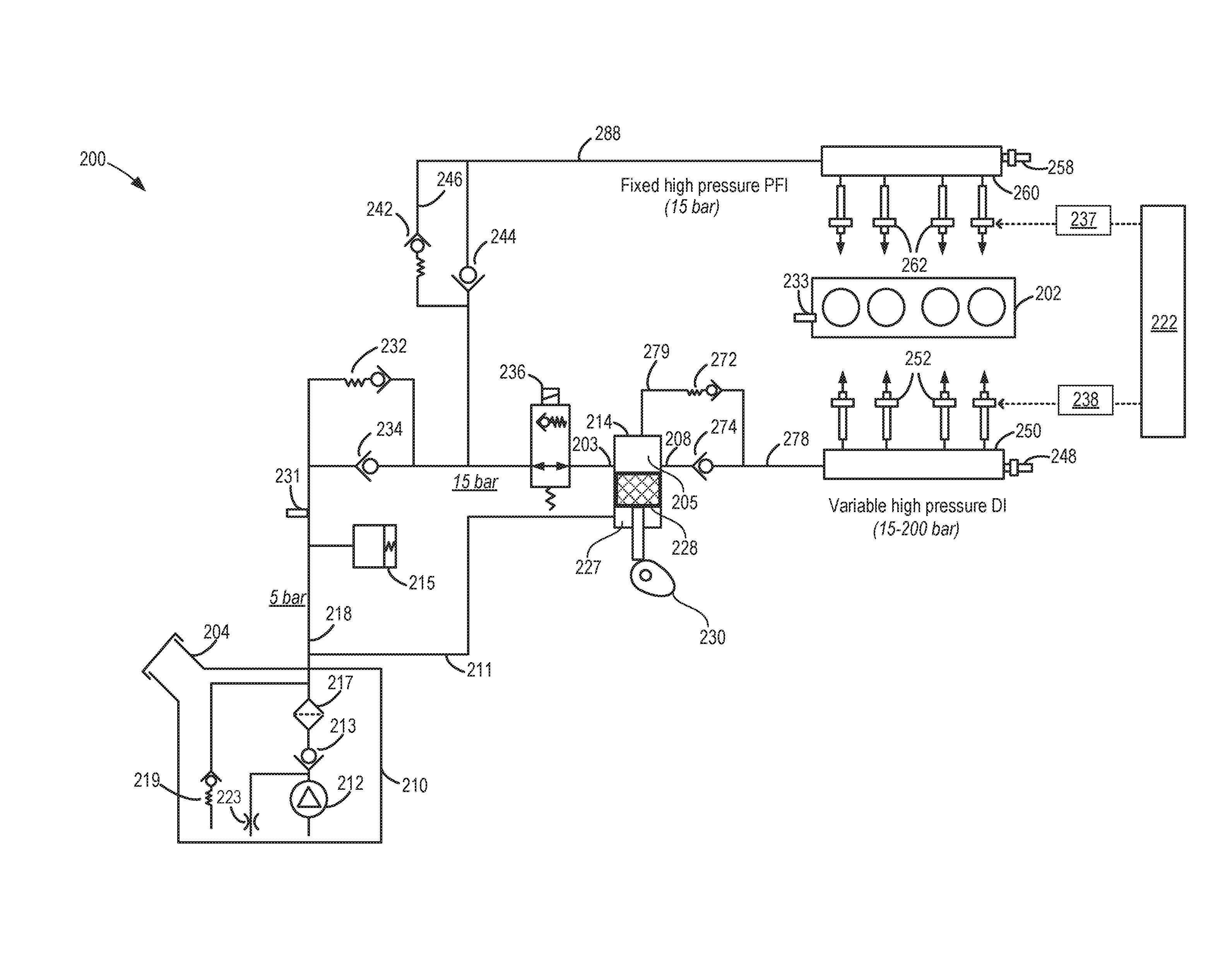
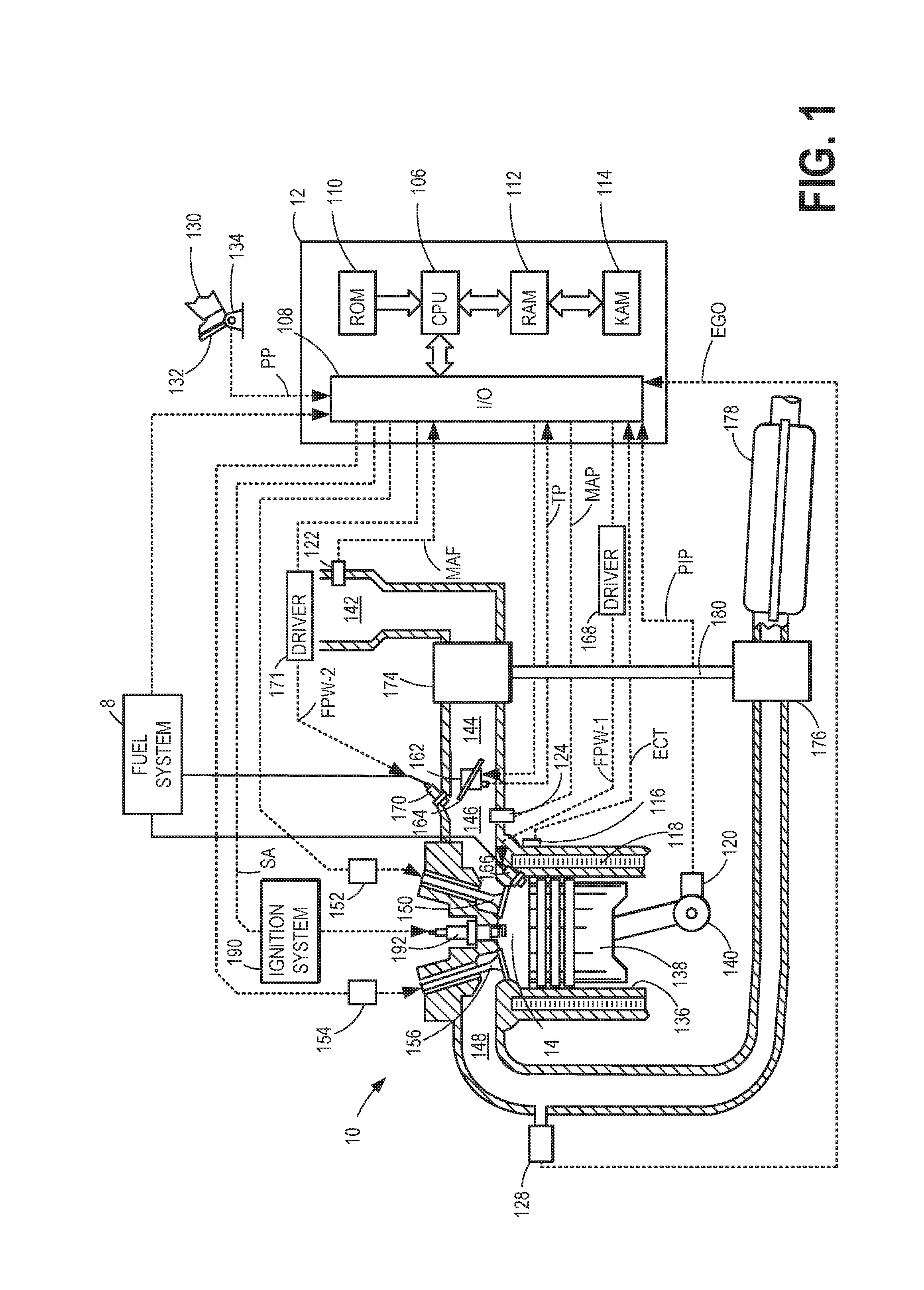
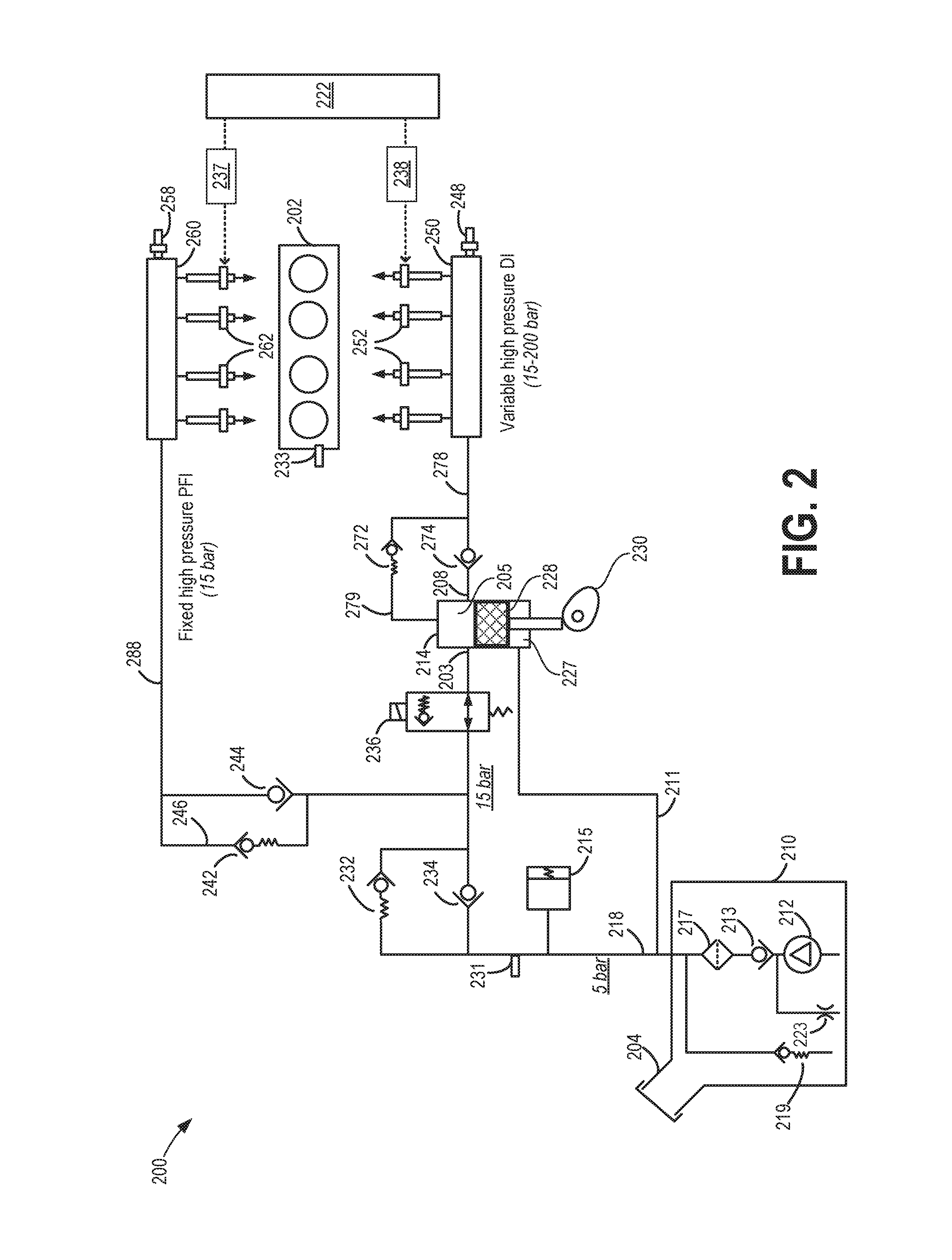
[0017]The following detailed description provides information regarding a high pressure fuel pump and a system for reducing high pressure pump-induced pressure fluctuations at a port injection fuel rail. An example embodiment of a cylinder in an internal combustion engine is given in FIG. 1 while FIGS. 2-3 depict example fuel systems that may be used with the engine of FIG. 1. A controller may be configured to perform a control routine, such as the example routine of FIG. 4, to reposition a port injection fuel pulse so as to align a center of the fuel pulse with an average port injection fuel rail pressure. The port injection fuel rail pressure may be estimated based on fuel pump pressure and engine speed (FIGS. 6A-6B). An example repositioning of a port fuel injection pulse is shown at FIG. 5.

[0018]Regarding terminology used throughout this detailed description, a high pressure pump, or direct injection pump, may be abbreviated as a DI or HP pump. Similarly, a low pressure pump, or...


PUM


Abstract

Methods and systems are provided for reducing fueling errors resulting from pressure pulsations in a port injection fuel rail. The pressure pulsations result from pressure pulsations generated in a high pressure fuel pump delivering fuel to both the port injection fuel rail and a direct injection fuel rail. A center of a port injection fuel pulse is positioned on an average pressure-crossing of the pressure pulsations so as to cancel out the effect of the over-average and under-average pressure pulsations.

Description

CROSS REFERENCE TO RELATED APPLICATION[0001]The present application claims priority to U.S. Provisional Patent Application No. 62 / 175,059, entitled “Methods and Systems for Dual Fuel Injection,” filed on Jun. 12, 2015, the entire contents of which are hereby incorporated by reference for all purposes.FIELD[0002]The present description relates to systems and methods for adjusting operation of an internal combustion engine that includes high pressure port and direct fuel injectors.BACKGROUND AND SUMMARY[0003]Direct fuel injection (DI) systems provide some advantages over port fuel injection systems. For example, direct fuel injection systems may improve cylinder charge cooling so that engine cylinders may operate at higher compression ratios without incurring undesirable engine knock. However, direct fuel injectors may not be able to provide a desired amount of fuel to a cylinder at higher engine speeds and loads because the amount of time a cylinder stroke takes is shortened so that ...

Claims


Application Information

Patent Timeline
IPC IPC(8): F02M37/00F02M63/02
CPCF02M63/029F02M37/0041F02D41/0025F02D41/3845F02D41/401F02D2200/101F02D41/3094F02D2041/3881F02D2200/0604F02D2250/04Y02T10/40F02D41/34F02M59/00F02M63/00
Inventor SANBORN, ETHAN D.HOLLAR, PAULDUSA, DANIELTHOMAS, JOSEPH LYLE
Owner FORD GLOBAL TECH LLC
Learn More