Methods and systems for fixed and variable pressure fuel injection

a technology of variable pressure and fuel injection, which is applied in the direction of liquid fuel feeders, machines/engines, electric control, etc., can solve the problems of insufficient time, inability to provide the desired amount of fuel to the cylinder, and the engine may develop less power than is desired, so as to improve the cooling of the cylinder, less power, and higher compression ratio

Active Publication Date: 2016-06-16
FORD GLOBAL TECH LLC
View PDF5 Cites 21 Cited by
  • Summary
  • Abstract
  • Description
  • Claims
  • Application Information

AI Technical Summary

Benefits of technology

[0002]Direct fuel injection (DI) systems provide some advantages over port fuel injection systems. For example, direct fuel injection systems may improve cylinder charge cooling so that engine cylinders may operate at higher compression ratios without incurring undesirable engine knock. However, direct fuel injectors may not be able to provide a desired amount of fuel to a cylinder at higher engine speeds and loads because the amount of time a cylinder stroke takes is shortened so that there may not be sufficient time to inject a desired amount of fuel. Consequently, the engine may develop less power than is desired at higher engine speeds and loads. In addition, direct injection systems may be more prone to particulate matter emissions.

Problems solved by technology

However, direct fuel injectors may not be able to provide a desired amount of fuel to a cylinder at higher engine speeds and loads because the amount of time a cylinder stroke takes is shortened so that there may not be sufficient time to inject a desired amount of fuel.
Consequently, the engine may develop less power than is desired at higher engine speeds and loads.
In addition, direct injection systems may be more prone to particulate matter emissions.
One issue with such high pressure DI systems is that the dynamic range of the injectors may be limited by the rail pressure.
These conditions can result in large fueling errors.

Method used


Image

  • Methods and systems for fixed and variable pressure fuel injection
  • Methods and systems for fixed and variable pressure fuel injection
  • Methods and systems for fixed and variable pressure fuel injection

Examples


Embodiment Construction

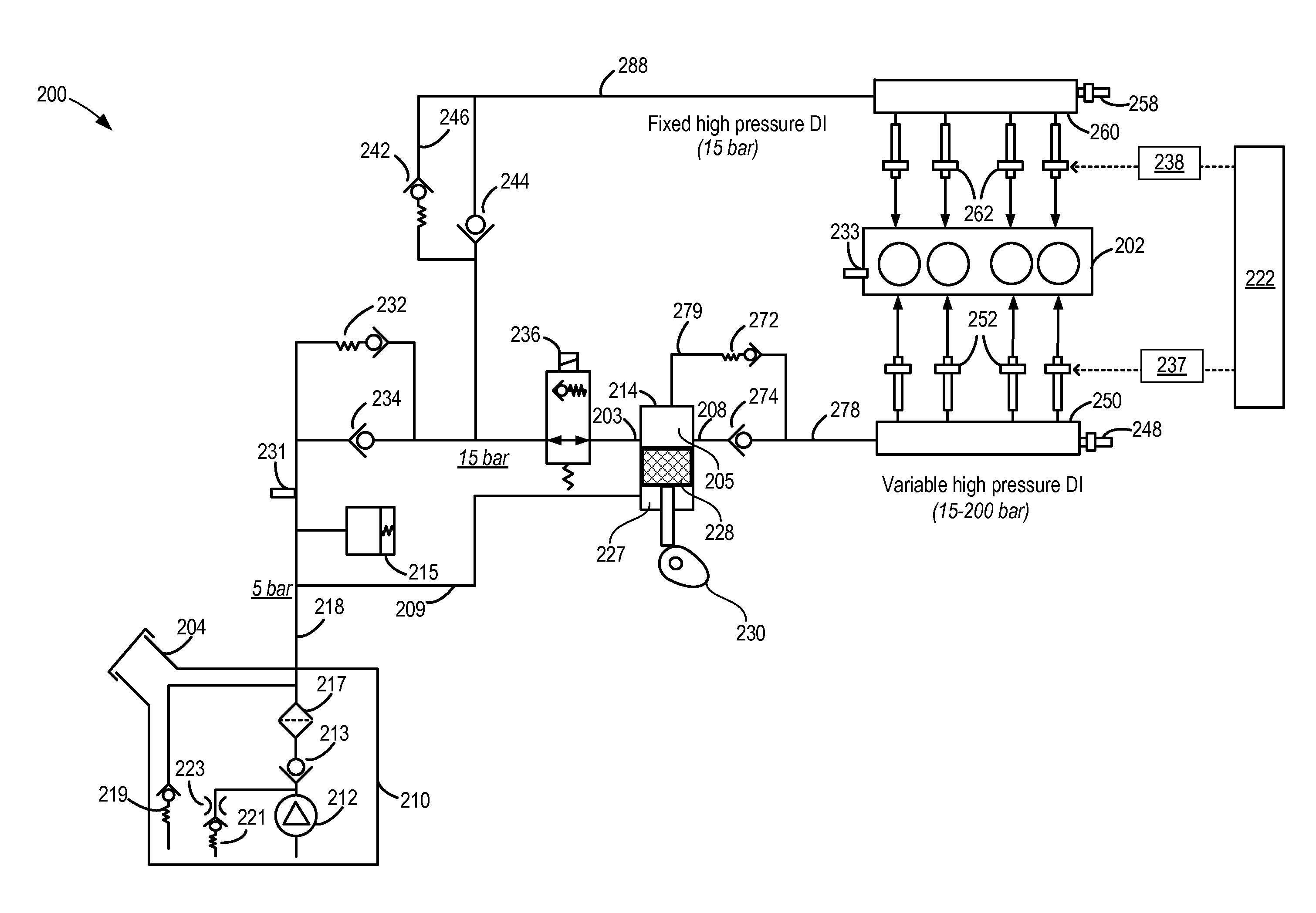
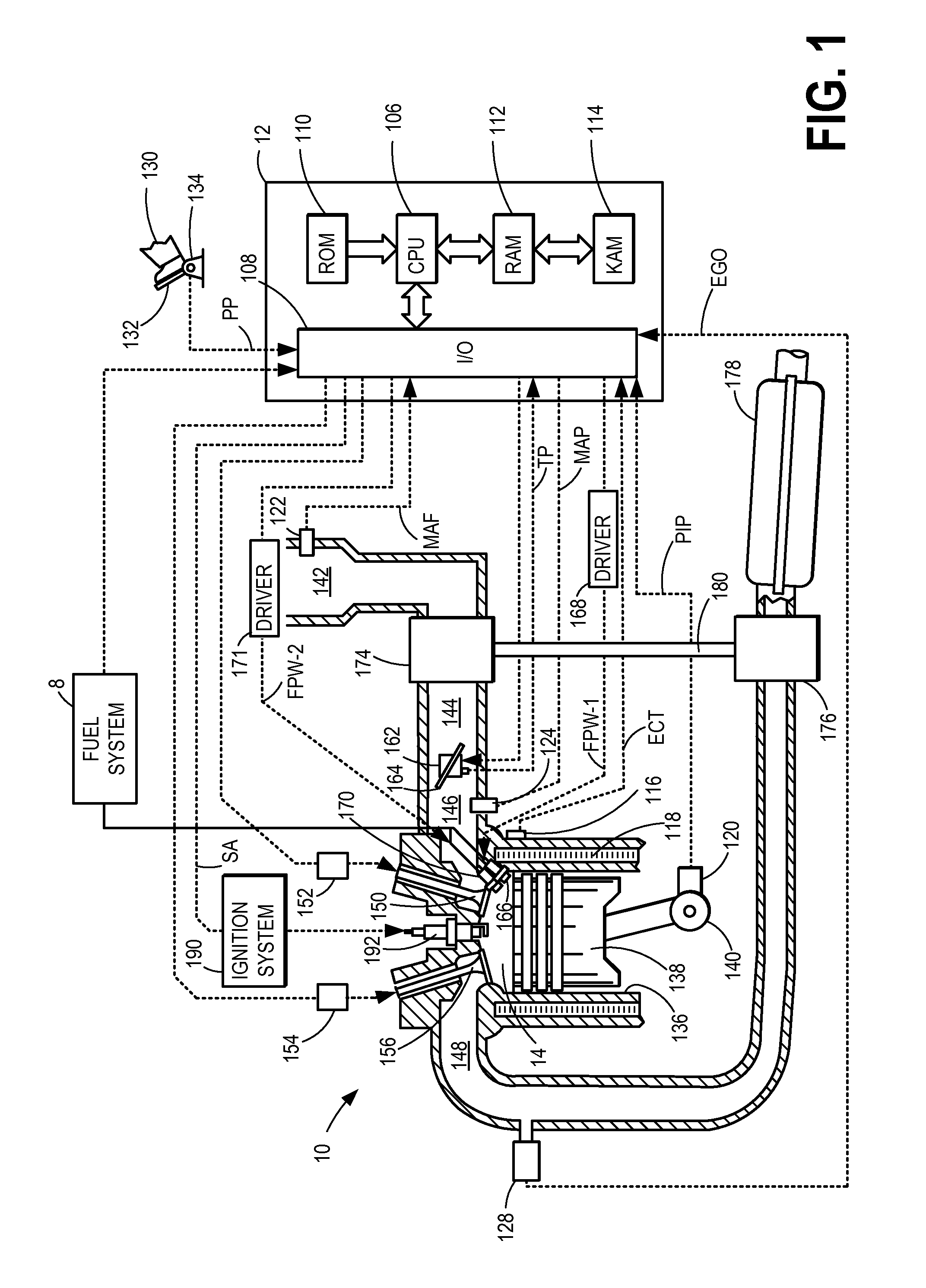
[0016]The following detailed description provides information regarding a high pressure fuel pump and a system for mechanically-regulating the pressure in each of a fixed pressure and variable pressure fuel rail coupled to direct injectors. An example embodiment of a cylinder in an internal combustion engine is given in FIG. 1 while FIG. 2 depicts a fuel system that may be used with the engine of FIG. 1. The high pressure pump with mechanical pressure regulation and related fuel system components shown in detail at FIG. 2 enable the fixed pressure direct injection fuel rail to be operated at a pressure higher than the default pressure of a lift pump while concurrently enabling the variable pressure direct injection fuel rail to be operated in a variable high pressure range. A method for adjusting fuel delivery via the direct injection fuel rails is shown with reference to FIG. 3. For example, direct injection at the fixed pressure may be used at an engine cold-start due to the limit...


PUM


Abstract

Methods and systems are provided for operating a high pressure injection pump to provide each of high fixed fuel pressure at a first direct injection fuel rail and high variable fuel pressure at a second direct injection fuel rail. The direct injection fuel rail pressure can be raised above a pressure provided with a lift pump via a fuel system configuration that includes various check valves, pressure relief valves, and a spill valve positioned between an inlet of the high pressure injection pump and the port injection fuel rail. Fixed and variable high pressure direct injection may be advantageously used to provide learn the ballistic region of each direct injector.

Description

FIELD[0001]The present description relates to systems and methods for adjusting operation of fuel injectors for an internal combustion engine. The methods may be particularly useful for an engine that includes fixed and variable high pressure direct fuel injectors.BACKGROUND AND SUMMARY[0002]Direct fuel injection (DI) systems provide some advantages over port fuel injection systems. For example, direct fuel injection systems may improve cylinder charge cooling so that engine cylinders may operate at higher compression ratios without incurring undesirable engine knock. However, direct fuel injectors may not be able to provide a desired amount of fuel to a cylinder at higher engine speeds and loads because the amount of time a cylinder stroke takes is shortened so that there may not be sufficient time to inject a desired amount of fuel. Consequently, the engine may develop less power than is desired at higher engine speeds and loads. In addition, direct injection systems may be more p...

Claims


Application Information

Patent Timeline
Patent Type & Authority Applications(United States)
IPC IPC(8): F02D41/38F02D41/02F02D41/24F02D41/06F02M63/02F02M37/00
CPCF02D41/3863F02M63/023F02M37/0023F02D2041/389F02D41/064F02D41/0235F02M63/0285F02D41/2461F02D41/3082F02D41/3094F02D41/3836F02D41/3845F02D2041/3881F02D2250/31F02M37/0029F02M55/025F02D41/2467F02D41/3854F02D41/406F02M63/029Y02T10/40
Inventor SURNILLA, GOPICHANDRABASMAJI, JOSEPH F.MEINHART, MARKPURSIFULL, ROSS DYKSTRA
Owner FORD GLOBAL TECH LLC
Why Eureka
Try Eureka