Remote camera relay controller method and apparatus

a relay controller and remote camera technology, applied in the field of remote digital camera operation, can solve the problems of lack of image transfer capability, low resolution images, and no prior art device describes a combination of features

Inactive Publication Date: 2002-06-04
CONOVAL PAUL
View PDF14 Cites 187 Cited by
  • Summary
  • Abstract
  • Description
  • Claims
  • Application Information

AI Technical Summary

Benefits of technology

It is one of the goals of this invention to provide a universal adapter to be used with various commercial digital camera products, giving the camera an ability to be operated remotely over a communications link as seamlessly as a direct camera-to-host connection.

Problems solved by technology

Virtually all of the real-time video-teleconferencing products however, result in relatively low-resolution images due to phone line bandwidth limitations when used for real-time video.
The image acquisition means of prior art devices are generally integral to the transmission means and don't allow for a modular attachment and remote positioning of the camera component.
U.S. Pat. No. 5,682,557 however, describes a controller unit for a film camera which is attachable and detachable from the camera body, but lacks image transfer capability.
None of the prior art devices describe a combination that provides for the universal adaptation of a small, self-contained, digital camera that allows for transparent remote control and positioning for field-of-view selection with access control permissions.
Further, none have the. ability to pass command, control and image data between a host viewer and remote camera over a transparent forwarding communications link, independent of specific camera communications protocols and data formats.
These include a relatively expensive installation, large size due to the aggregate combination of separate components, significant power utilization not suitable for continuous battery operation and incompatibility with outdoor use.

Method used


Image

  • Remote camera relay controller method and apparatus
  • Remote camera relay controller method and apparatus
  • Remote camera relay controller method and apparatus

Examples


Embodiment Construction

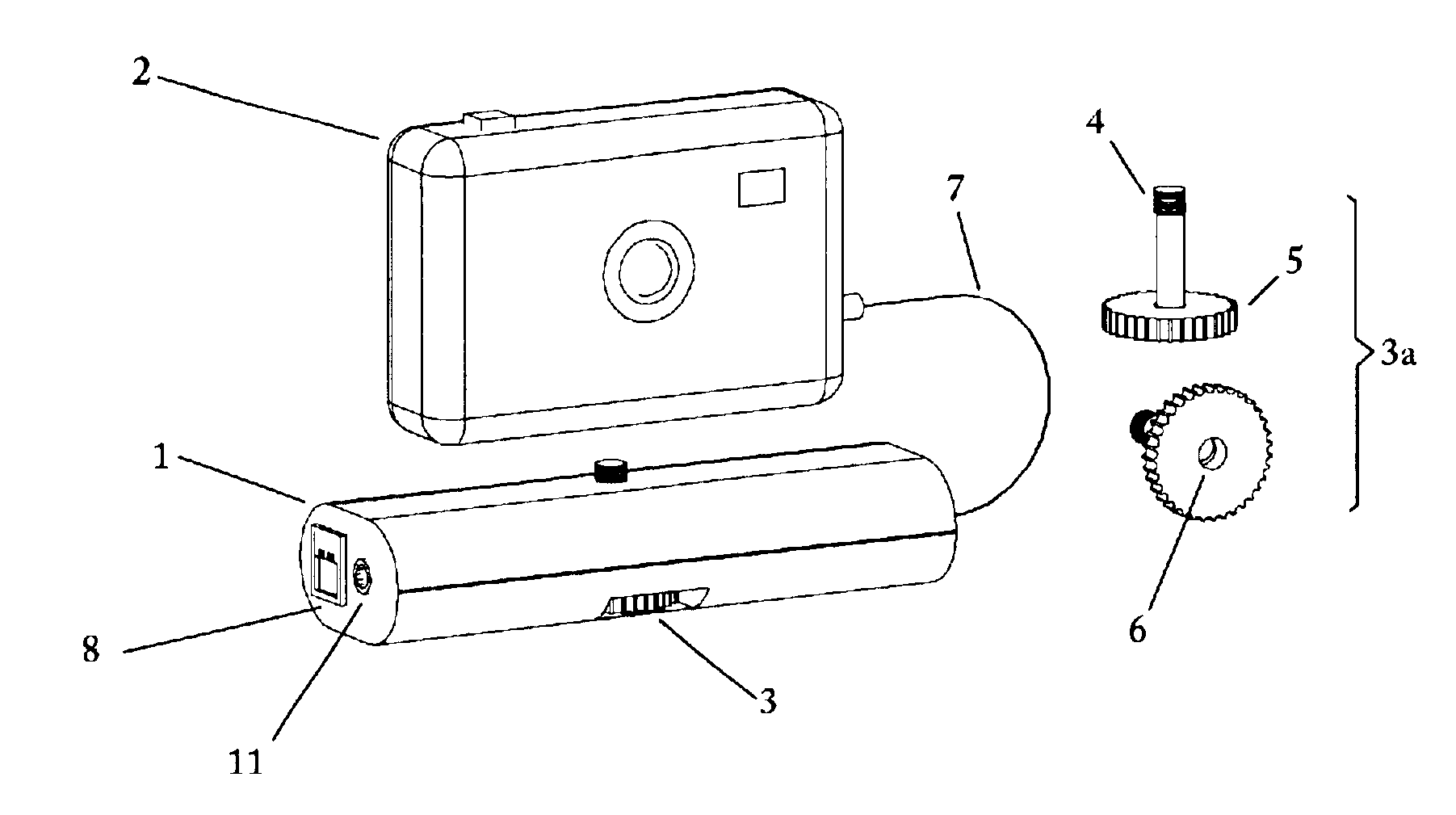
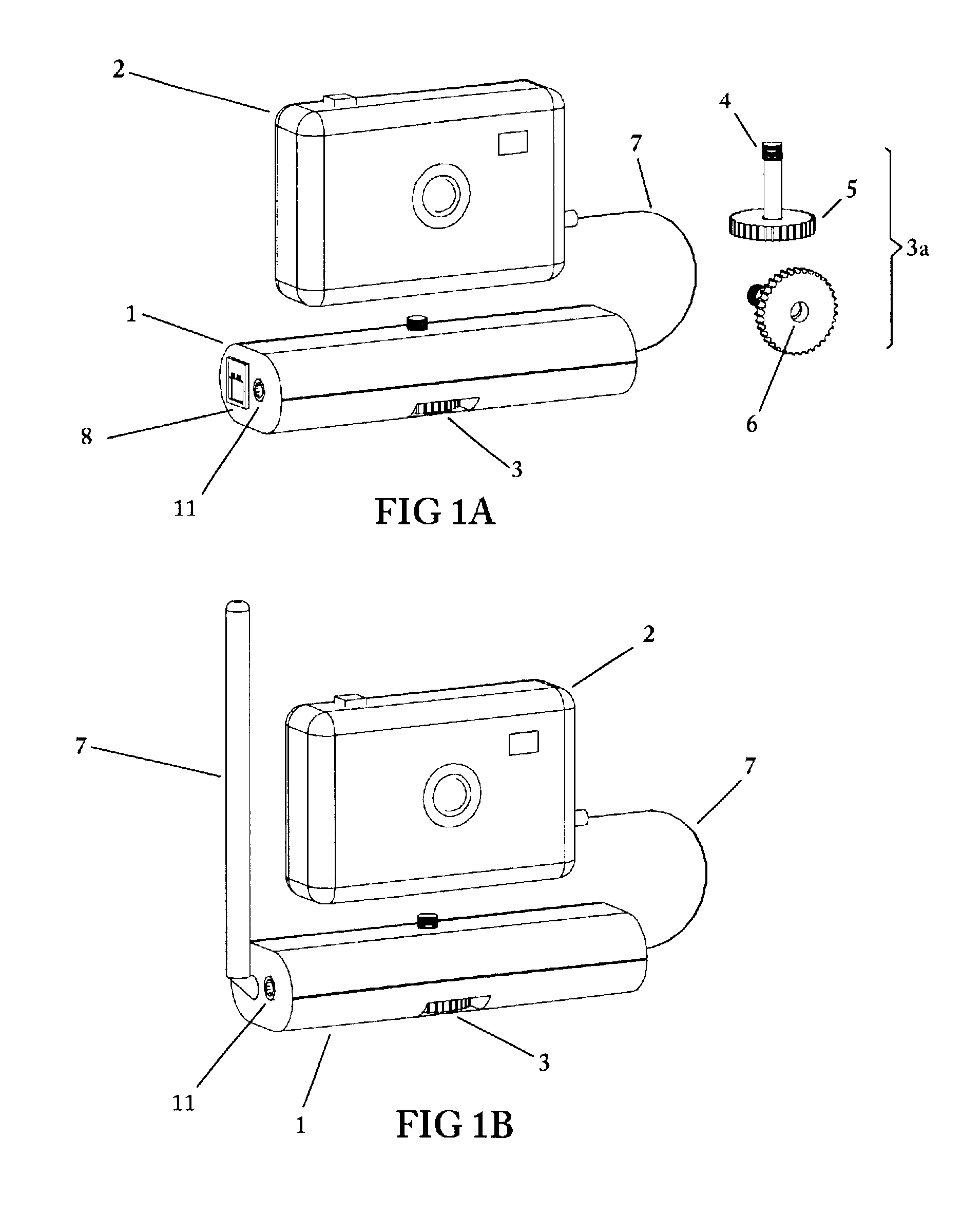
Referring to FIG. 1A, an overall view of the remote relay controller in relation to an external digital camera is shown. In this configuration, communications between the remote relay controller and a local processor is accomplished by means of a modem. Digital camera 2 attaches to enclosure 1, which contains the relay controller electronics and modem, by means of mounting screw assembly 3. A detail of mounting screw assembly 3 is shown as 3a which includes a threaded mounting screw 4 on one end and a knurled knob 5 on the opposite end. Knurled knob 5 has embedded therein, a threaded cavity 6 for receiving a reciprocal threaded screw for attachment of an additional mounting device such as a tripod, bracket or the like.

Mounting screw 4 has a standard thread dimension such as that typically used to attach photographic equipment to a tripod stand. Mounting screw assembly 3 passes through enclosure 1 as shown. Attachment of camera 2 to enclosure 1 is accomplished by tightening screw 4 w...


PUM


Abstract

A remote camera relay method and apparatus for remotely operating a self-contained, unattended digital camera over a communications link. Format conversion means are included for transparently relaying control signals and remote image data between a local host processor and the remotely located digital camera, independently of specific camera command and image protocols. It thereby functions as a universal remote image transmission adapter, operable as an attachment for use with self-contained digital cameras. A portable enclosure is provided for accommodating the remote relay communications and control electronics and for attaching a hand-held digital camera thereto. Further means are included for remotely actuating the pan and tilt orientation of the camera in accordance with field-of-view selection commands. Data rate conversion and error correction coding are included for providing reliable, low power image forwarding. The communications channel could be a dial-up telephone system, a network connection, modem, an infra-red link or a wireless RF link, for example. Additional control means are provided for remotely selecting the camera field of view for image capture, and includes the ability to access only those subsets of image scenes for which viewing permissions are authorized. A further mode of operation includes protocol training whereby host photographing commands are captured by the remote relay invention during on-line operation, then replayed at programmed times resulting in automatic scheduled remote image capture. Power management is provided for maximizing operating time when used in low power, portable, battery operation.

Description

BACKGROUND OF INVENTIONThis invention relates to remote digital camera operation for controlling digital camera functions, transferring digital images and controlling camera orientation over a communications link. It combines the arts of digital camera technology and communications methods. In many applications there is a need to control camera functions and to view the resulting images from distant locations. Examples include the viewing of naturalistic and scientific observations, observing construction site progress, monitoring of unoccupied residences such as vacation property, surveillance and any other application where visual observation from a distant location is desired. It is also of significant value to remotely orient the camera in order to transmit various views with a single camera. For many of these applications the need for high-resolution images is more important than for real-time remote viewing. The present invention adapts the use of a self-contained digital came...

Claims


Application Information

Patent Timeline
Patent Type & Authority Patents(United States)
IPC IPC(8): H04N5/232
CPCH04N5/23206H04N5/23203H04N23/66H04N23/661H04N23/65H04N23/695
Inventor CONOVAL, PAUL
Owner CONOVAL PAUL
Why Eureka
Try Eureka