
Method for sending channel quality information in a multi-carrier radio communication system, corresponding mobile terminal and base station

Inactive Publication Date: 2006-07-27
ALCATEL LUCENT SAS
View PDF6 Cites 103 Cited by
  • Summary
  • Abstract
  • Description
  • Claims
  • Application Information

AI Technical Summary

Benefits of technology

[0014] The method according to the present invention presents the advantage to reduce the signaling load on the feedback signaling channel while enabling it to refine the sub-carrier quality information when the mobility grade of the mobile terminal enables it. This results in an efficient resource allocation leading to an increased throughput in the network.
[0015] The method according to the present invention further presents the advantage to reduce the interference since the reduced load on the feedback signaling channel enables a transmission with a reduced transmitting power. For the same reason, the present invention presents the advantage to increase the battery life of user terminal reporting the channel quality information on the feedback signaling channel.

Problems solved by technology

Such sub-carriers would be useless allocated to this user because of fading.
In the ideal case, the UE should make a channel quality measurement for each sub-carrier and report it on the feedback channel to the Node B. The drawback is that this would represent a huge amount of signaling information (some Mbits) especially in multi carrier system with up to thousands of sub-carriers.

Method used


Image

  • Method for sending channel quality information in a multi-carrier radio communication system, corresponding mobile terminal and base station
  • Method for sending channel quality information in a multi-carrier radio communication system, corresponding mobile terminal and base station
  • Method for sending channel quality information in a multi-carrier radio communication system, corresponding mobile terminal and base station

Examples


Embodiment Construction

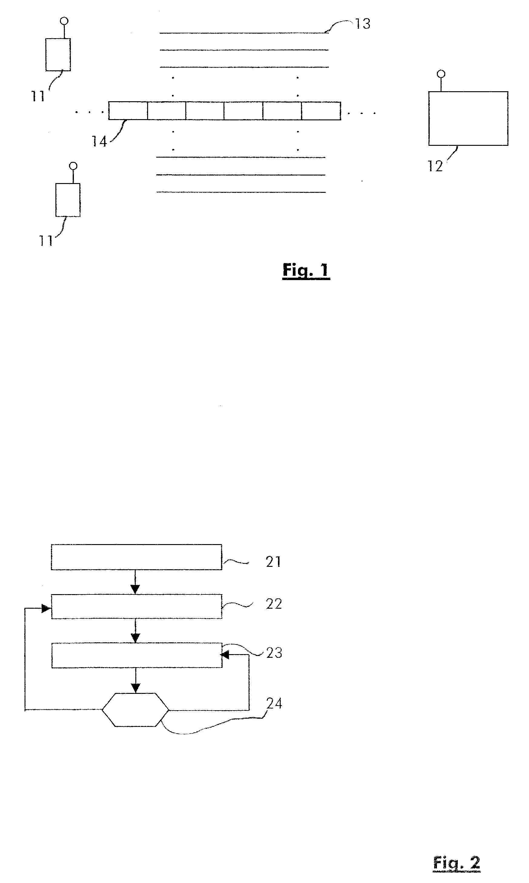
[0021]FIG. 1 shows an illustration of a network using multi-carrier transmission in the downlink and a feedback signaling channel in the uplink. Mobile terminals 11 are receiving multi-carrier frequency signals in the downlink from base station 12 over a plurality of sub-carriers 13. On the uplink, mobile terminals 11 send signaling information to base station 12 on a feedback signaling channel 14.

[0022] The multi-carrier network may comprises 256, 512 or up to thousands of sub-carriers which are allocated to mobile terminals 11. Preferably, several sub-carriers 13 are allocated to each mobile terminal 11 in order to match the high throughput received from base station 12 in the downlink. The frequency separation between the sub-carriers is chosen so that the sub-carriers are orthogonal to one another (i.e. the data transmitted on one sub-carrier is not causing interference on the data sent on the other sub-carriers).

[0023] According to the present invention, mobile terminals are ...


PUM


Abstract

The present invention relates to a method for sending channel quality information in a multi-carrier radio communication system comprising at least one mobile terminal and at least one base station, said channel quality information being sent on a signaling channel by said mobile terminal to said base station. According to the present invention, the method comprises the steps of: performing channel quality measurements on a plurality of frequency sub-carriers; generating and sending a first report over said signaling channel, said first report comprising a first channel quality information depending on said channel quality measurements on at least one sub-carrier, said at least one sub-carrier building an herein called first group of sub-carriers; determining a number of additional reports depending on the mobility grade of said mobile terminal; if said number of additional reports is not reached, generating and sending an additional report over said signaling channel comprising an additional channel quality information depending on channel quality measurements on at least one sub-carrier, said at least one sub-carrier building an herein called second group of sub-carriers, said second group of sub-carriers being different of said first group of sub-carriers.

Description

BACKGROUND OF THE INVENTION [0001] The invention is based on a priority application EP052901 77.4 which is hereby incorporated by reference. [0002] The present invention relates to a method for optimizing the use of the feedback channel in multi-carrier systems. [0003] Such multi-carrier systems often implement Orthogonal Frequency Division Multiplexing (OFDM) as multi-carrier transmission technique. OFDM is for example used in the HIPERLAN / 2 standard as well as an extension of the IEEE 802.11a standard for the 5 Ghz area. OFDM could also offer a sensible alternative for high-speed mobile applications, and thus represents an important step for next generation mobile radio systems or for a 4th generation air interface. To this extend, the 3rd Generation Partnership Project (3GPP), for the standardization of high-speed broadband wireless mobile communication systems, is recently considering the application of OFDM techniques for the high speed data packet access (HSDPA) air interface ...

Claims


Application Information

Patent Timeline
IPC IPC(8): H04K1/10
CPCH04L1/0003H04L1/0026H04L27/2601
Inventor WUNDER, GERHARDZHOU, CHANKAMINSKI, STEPHENBAKKER, HAJO
Owner ALCATEL LUCENT SAS
Learn More