Multi-channeled micro-structured reactor

A microstructure reactor and multi-channel technology, applied in chemical methods, chemical instruments and methods, chemical/physical/physicochemical processes for reacting liquid and gaseous media, can solve the problems that cannot meet the needs of large-scale production of chemical processes Problems such as expensive processing costs and high equipment costs, to achieve the effect of low operating costs, simple equipment, and large equipment processing capacity

Active Publication Date: 2006-02-22
TSINGHUA UNIV
View PDF0 Cites 51 Cited by
  • Summary
  • Abstract
  • Description
  • Claims
  • Application Information

AI Technical Summary

Problems solved by technology
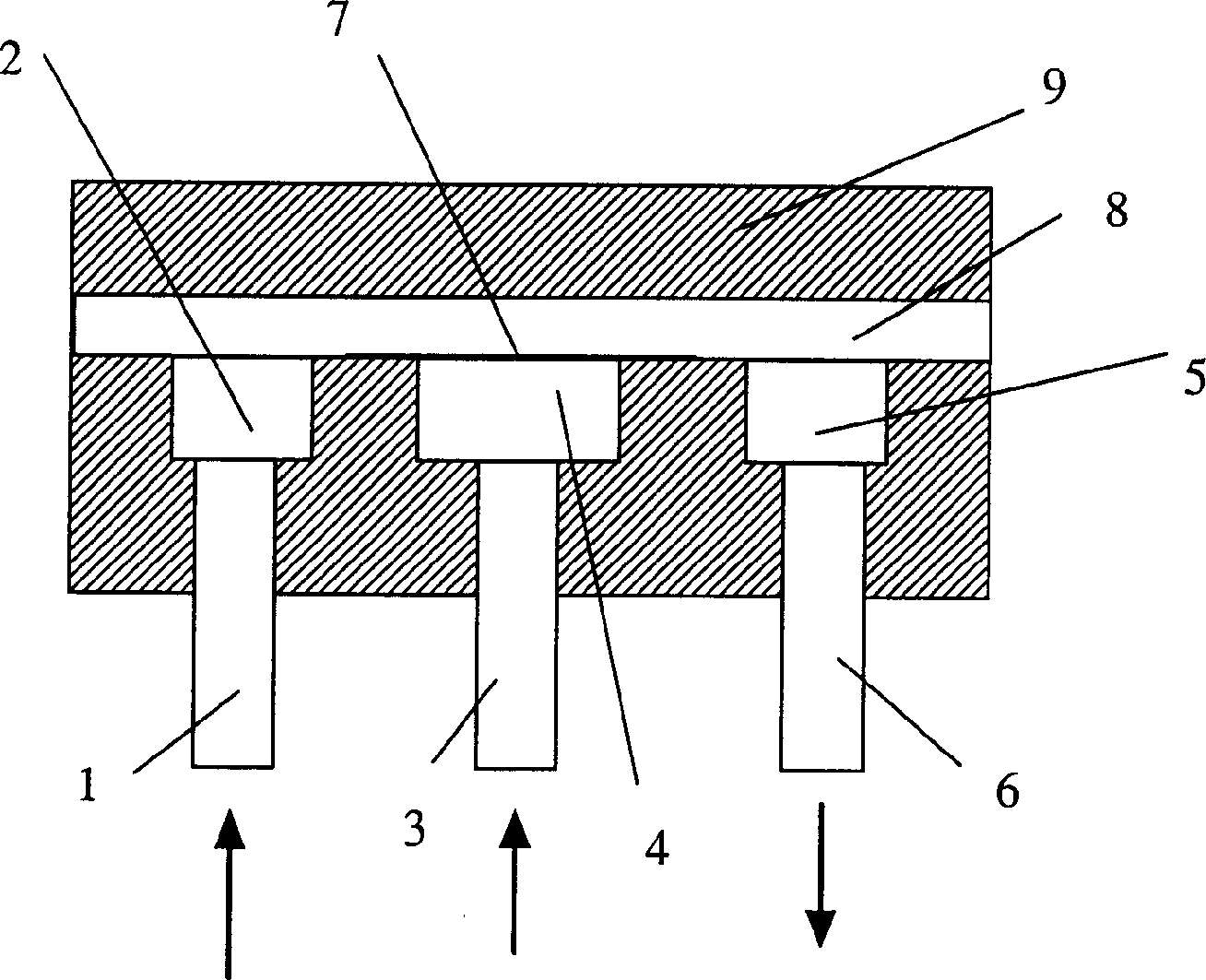
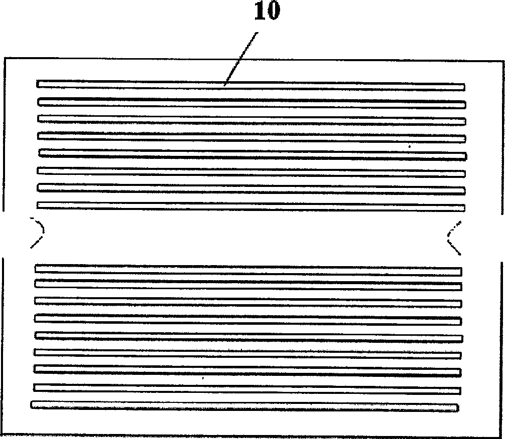
However, due to the limitation of size, microchannel reactors are only suitable for clean material systems; their processing capacity is small, which cannot meet the large-scale production of chemical processes; and the processing cost is high, and the equipment cost is high, which limits their application in large-scale large-scale industrial production process

Method used


Image

  • Multi-channeled micro-structured reactor
  • Multi-channeled micro-structured reactor

Examples


Embodiment 1

[0015] A 4% caustic soda solution is used as the dispersed phase, gasoline with a petroleum acid content of 2.061 mgKOH / g is used as the continuous phase, and a 10-micron stainless steel porous medium is used as the dispersed medium, and a microstructure reactor containing 10 parallel channels in the continuous phase parallel channel plate Medium reaction deacidification, when the ratio (continuous phase volume flow rate: dispersed phase volume flow rate) is 20:1, the deacidification rate is 98%, the acid value after alkali washing is less than 0.04mgKOH / g, and the gasoline processing capacity can reach 320L / h, the processing capacity of each channel is 32L / h.

Embodiment 2

[0017] Using 4% caustic soda solution as the continuous phase, diesel oil with a petroleum acid content of 1.455mgKOH / g as the dispersed phase, and using a 20-micron stainless steel microfiltration membrane as the dispersion medium, mixed deacidification in a microstructure reactor containing 20 parallel channels , when the ratio (dispersed phase flow rate: continuous phase flow rate) is 30:1, the deacidification rate is 93%, the acid value after alkali washing is less than 0.06mgKOH / g, and the diesel oil treatment capacity can reach 4000L / h, each channel The processing capacity is 200L / h.

Embodiment 3

[0019] Using fuming sulfuric acid as the dispersed phase, 10% cyclohexane carboxylic acid n-hexane solution as the continuous phase, and using 1 micron stainless steel microfiltration membrane as the dispersion medium, cyclohexane was reacted in a microstructure reactor containing 5 parallel channels For alkanoic anhydride, when the ratio (continuous phase flow rate: dispersed phase flow rate) is 50:1, measure the remaining cyclohexanecarboxylic acid concentration in the normal hexane solution after the reaction, and obtain the reaction conversion rate based on cyclohexanecarboxylic acid It is 85%, the selectivity is 99%, the continuous phase flow rate is 20L / h, and the processing capacity of each channel is 4L / h.


PUM


Abstract

Disclosed is amultichannel reactor with microstructure. Continuous phase inlet pipe and distribution chamber, discontinuous phase inlet pipe and distribution chamber, mixture phase buffer chamber and fluid outlet pipe connects separately, and they compose the lower cavity. Porous distribution medium is sealed in the upper distribution chamber of discontinuous phase. A parallel channel plate of continuous phase is located above the lower cavity and the upper is sealed. The continuous phase liquid flows into the reactor from the distribution chamber of inlet pipe; the discontinuous liquid flows into the parallel channel of continuous phase following through the distribution medium, distributes into minute drop or air bubble with the floating shearing force of continuous phase liquid, and then connects with the continuous phase liquid to realize the rapid mixture and reaction of the two- phase liquid; then the liquid flows out of the reactor. With the invention, the area of mass transfer is big, the reaction conversion rate is high, and large scale production can be realized.

Description

technical field [0001] The invention relates to a high-performance reactor for rapid mixing and reaction of fluids in chemical process, in particular to a multi-channel microstructure reactor for rapid mixing and reaction of two fluids, which belongs to the rapid mixing and reaction of chemical process equipment [0002] technology field. Background technique [0003] In many fields such as chemistry, chemical industry, petrochemical, pharmaceutical and food, especially the reaction and separation process of chemical industry, it is necessary to carry out the mixing and reaction between two or more strands of materials, and the mixing performance has a very important influence on the reaction process. Commonly used reaction equipment includes fully mixed tanks and plug flow reactors, etc., which have a large processing capacity and can meet the requirements of large-scale industrial production, but have the disadvantages of poor mixing effect, large equipment volume and lon...

Claims


Application Information

Patent Timeline
Patent Type & Authority Applications(China)
IPC IPC(8): B01J19/00B01J10/00
Inventor 徐建鸿骆广生吕阳成王玉军陈桂光
Owner TSINGHUA UNIV
Why Eureka
Try Eureka