
Non-invasive energy upconversion methods and systems for in-situ photobiomodulation

a photobiomodulation and in-situ technology, applied in the direction of energy modified materials, dianostics using fluorescence emission, granular delivery, etc., can solve the problems of photon emission, complex combination of wavelength, intensity, duration and treatment interval, and veins to permanently close and disappear

Active Publication Date: 2011-01-27
DUKE UNIV +1
View PDF28 Cites 227 Cited by
  • Summary
  • Abstract
  • Description
  • Claims
  • Application Information

AI Technical Summary

Benefits of technology

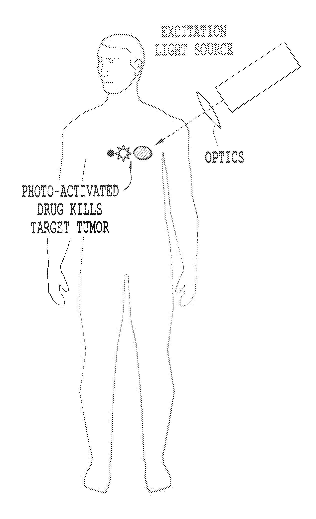
The present invention provides a method for modifying a target structure in a subject that mediates or is associated with a biological activity to treat a condition, disorder or disease. The method involves placing a nanoparticle in the vicinity of the target structure and exposing it to a first wavelength of radiation to generate a second wavelength of radiation with higher energy. The nanoparticle is designed to emit light in the vicinity of or into the target structure upon interaction with an initiation energy source. The emitted light induces a predetermined change in the target structure, which can be a modification, inhibition, or death of the cells. The method is non-invasive and can treat disorders by non-invasive or minimum invasive techniques.

Problems solved by technology

Relaxation from these energy states results in photon emission.
The “best” combination of wavelength, intensity, duration and treatment interval is complex and sometimes controversial with different diseases, injuries and dysfunctions needing different treatment parameters and techniques.
When the laser is slowly withdrawn, heat is applied to the vein walls, causing the vein to permanently close and disappear.
In patients with Parkinson's disease, for example, researchers have shown that electrical “deep brain stimulation” of cells can help patients, but they don't know precisely why.
That could lead to making the electrical treatment, which has some unwanted side effects, more targeted.
The laser systems currently used for biostimulation do not allow performing photobiomodulation in a region deep within thick tissue without a surgical invasion.
It is further well recognized that another problem associated with the existing methods of photobiomodulation is in differentiation of normal cells from target cells.
However, given that only a small percentage of the body's lymphocytes are treated, this seems unlikely to be the only mechanism of action.
However, there are still many limitations to ECP.
It requires establishing peripheral intravenous line or central venous access, which may be difficult to do in certain disease states such as systemic sclerosis or arthritis.
There is also a risk of infection at the venous or central line site, or in the central line catheter.
Further, it requires removing typically several hundred milliliters of whole blood from the patient, hence, the treatment is limited to patients who has sufficiently large initial volume of blood to be withdrawn.
Risk of contracting blood-born pathogen (Hepatitis, HIV, etc.) due to exposure to contaminated operating system is also a concern.
However, while a high yield of singlet oxygen is desirable it is by no means sufficient for a photosensitizer to be clinically useful.
Toxicity can become an issue if high doses of photosensitizer are necessary in order to obtain a complete response to treatment.
The preferential accumulation of PDT drug molecules in cancer cells combined with the localized delivery of light to the tumor, results in the selective destruction of the cancerous lesion.
It is not clear that direct damage to DNA is a major effect; therefore, this may indicate that photoactivation of DNA crosslinking is not stimulated efficiently.
Furthermore, when laser light is administered via external illumination of tissue surfaces, the treatment effect of PDT is confined to a few millimeters (i.e. superficial).
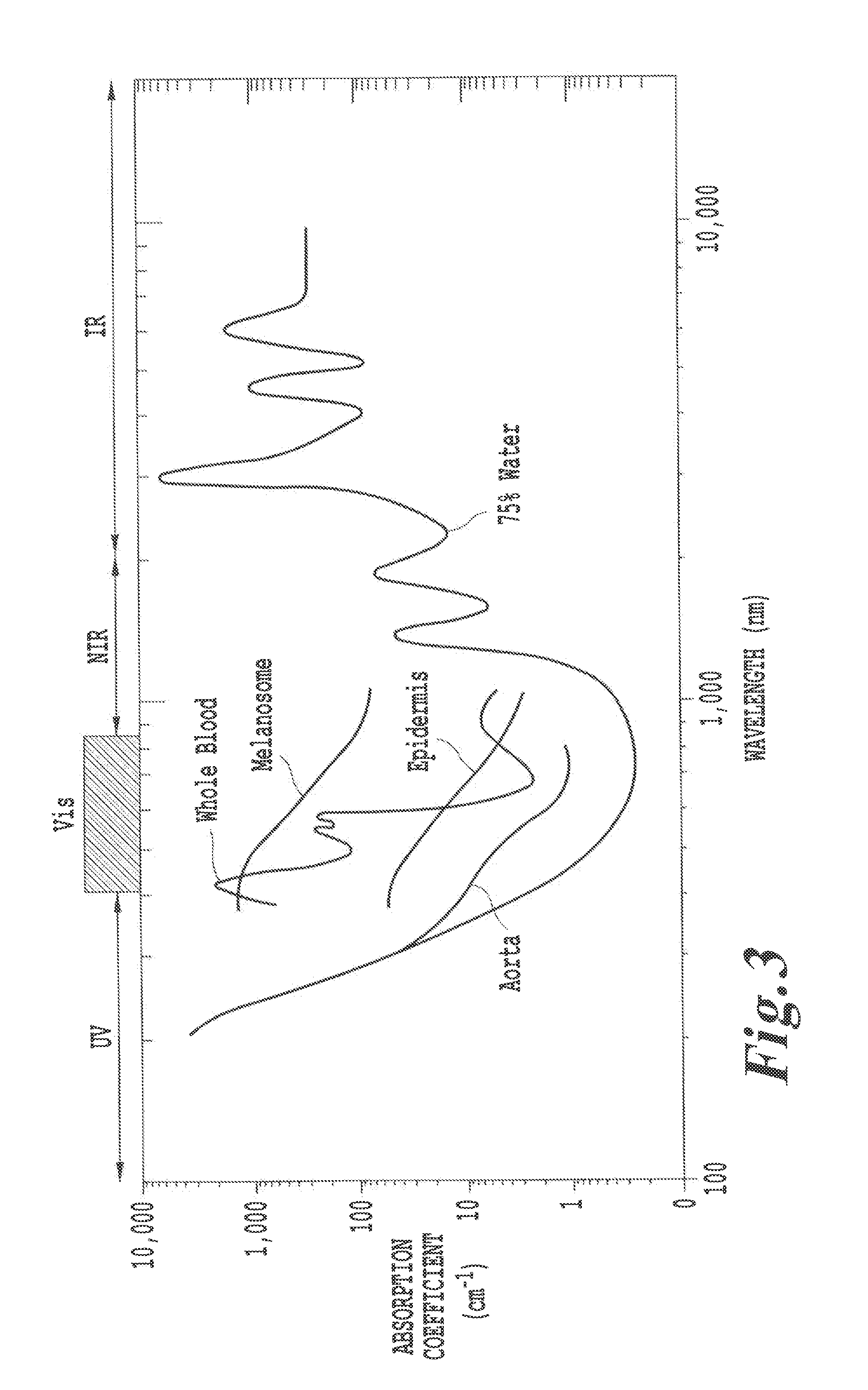
The reason for this superficial limitation is mainly the limited penetration of the visible light used to activate the photosensitizer.
However, even these treatments require significantly invasive techniques to treat the surface of the affected organs.
It is possible that the laser light and small amount of remaining microscopic and minimal gross disease results in too little or highly damaged structures.
It is not clear that direct damage to DNA is a major effect; therefore, this may indicate that photo activation of DNA crosslinking is not stimulated efficiently.
However, the percentage of patients eligible for this treatment is limited.
A survey of known treatment methods reveals that these methods tend to face a primary difficulty of differentiating between normal cells and target cells when delivering treatment, often due to the production of singlet oxygen which is known to be non-selective in its attack of cells, as well as the need to perform the processes ex vivo, or through highly invasive procedures, such as surgical procedures in order to reach tissues more than a few centimeters deep within the subject.
Another challenge for non-invasive therapeutic modalities is to have sufficient light energy to excite and photo-activate drug molecules deep inside tissue.
However, the use of NRI or UV radiation is known to penetrate tissue to only a depth of a few centimeters.
Also, this patent does not describe initiation energy sources emitting energy other than UV, visible, and near infrared energy; energy upgrading other than within the range corresponding to UV and IR light, and downgrading from high to low energy.
However, each suffers from the drawback that the treatment is dependent on the production of singlet oxygen to produce the desired effect on the tissue being treated, and is thus largely indiscriminate in affecting both healthy cells and the diseased tissue desired to be treated.
However, the method is not suitable for treating a patient and does not teach any mechanisms for stimulating the photosensitizers, indirectly.
However, the reference fails to disclose any mechanism of photoactivation using energy modulation agent that converts the initiation energy to an energy that activates the activatable pharmaceutical agent and also use of other energy wavebands, e.g., X-rays, gamma-rays, electron beam, microwaves or radio waves.
However, the reference fails to address any specific molecules for use in treating lymphomas or any other cancer.
Fluorescing photosensitizers are said to be preferred, but the reference does not teach how to select a system of fluorescent stimulation or photoactivation using fluorescent photosensitizers.
In addition, the reference teaches that 8-MOP is unsuitable for use as an antiviral, because it damages both cells and viruses.
It is well known that UV activation creates such reactive oxygen species, which are capable of seriously damaging otherwise healthy cells.
The use of psoralen and coumarin photosensitizers can give rise to alternative chemical pathways for dissipation of the excited state that are either not beneficial to the goal of viral inactivation, or that are actually detrimental to the process.
Both may lead to inactivating damage of tumor cells, viruses and healthy cells.
However, neither, alone or combined, lead to an auto vaccine effect.
While the complexity of the immune response and cytotoxic effects is fully appreciated by researchers, a therapy that harnesses the system to successfully stimulate an auto vaccine effect against a targeted, malignant cell has been elusive, except for extracorporeal photopheresis for treating lymphoma.
U.S. Pat. No. 6,235,508 teaches that 8-MOP and AMT are unacceptable photosensitizers, because each indiscriminately damages both cells and viruses.

Method used


Image

  • Non-invasive energy upconversion methods and systems for in-situ photobiomodulation
  • Non-invasive energy upconversion methods and systems for in-situ photobiomodulation
  • Non-invasive energy upconversion methods and systems for in-situ photobiomodulation

Examples


Embodiment Construction

>4 dielectric particles in the ˜20-150 nm size range.

[0139]FIG. 10A is a schematic illustration of other various upconverter structures of the invention.

[0140]FIG. 10B is another schematic illustration of other various upconverter structures of the invention.

[0141]FIG. 10C is a schematic illustration of plasmonics-active upconverter structures of the invention.

[0142]FIG. 10D is a schematic illustration of photo-active molecules linked to plasmonics-active upconverter structures of the invention.

[0143]FIG. 10E is a TEM micrograph of uncoated Y2O3 nanoparticles.

[0144]FIG. 10F is a TEM micrograph of gold coated Y2O3 nanoparticles of the invention.

[0145]FIG. 10G is X-ray diffraction data from gold coated Y2O3 nanoparticles of the invention.

[0146]FIG. 10H is a TEM micrograph of 15-nm gold nanoparticles prepared according to one embodiment of the present invention using the citrate reduction technique.

[0147]FIG. 10I is a TEM micrograph of 30-nm gold nanoparticles prepared according to one...


PUM

PropertyMeasurementUnit
diameteraaaaaaaaaa
diameteraaaaaaaaaa
diameteraaaaaaaaaa

Abstract

Products, compositions, systems, and methods for modifying a target structure which mediates or is associated with a biological activity, including treatment of conditions, disorders, or diseases mediated by or associated with a target structure, such as a virus, cell, subcellular structure or extracellular structure. The methods may be performed in situ in a non-invasive manner by placing a nanoparticle having a metallic shell on at least a fraction of a surface in a vicinity of a target structure in a subject and applying an initiation energy to a subject thus producing an effect on or change to the target structure directly or via a modulation agent. The nanoparticle is configured, upon exposure to a first wavelength λ1, to generate a second wavelength λ2 of radiation having a higher energy than the first wavelength λ1. The methods may further be performed by application of an initiation energy to a subject in situ to activate a pharmaceutical agent directly or via an energy modulation agent, optionally in the presence of one or more plasmonics active agents, thus producing an effect on or change to the target structure. Kits containing products or compositions formulated or configured and systems for use in practicing these methods.

Description

CROSS REFERENCE TO RELATED APPLICATIONS[0001]This application is related to U.S. patent application Ser. Nos. 11 / 935,655, filed Nov. 6, 2007 and 12 / 059,484, filed Mar. 31, 2008; U.S. patent application Ser. No. 12 / 389,946, filed Feb. 20, 2009; U.S. patent application Ser. No. 12 / 417,779, filed Apr. 3, 2009, U.S. patent application Ser. No. 12 / 725,108, filed Mar. 16, 2010, and provisional patent applications 61 / 161,328, filed Mar. 18, 2009, and 61 / 259,940, filed Nov. 10, 2009; the entire contents of each of which are hereby incorporated by reference. This application is also related to and claims priority from provisional patent applications 61 / 171,152, filed Apr. 21, 2009; the entire contents of each of which are hereby incorporated by reference.BACKGROUND OF THE INVENTION[0002]1. Field of Invention[0003]The present invention relates to methods and systems for treating a disorder or condition in a subject, that provide better distinction between normal, healthy cells and those cells...

Claims


Application Information

Patent Timeline
Patent Type & Authority Applications(United States)
IPC IPC(8): A61M37/00G02F1/01A61K35/12A61K39/00A61K9/16B82Y5/00
CPCA61K49/0039A61L2/08A61L2202/21A61L2202/22A61N2005/0656A61N5/02A61N5/0601A61N5/062A61N2005/0659A61N1/406A61B5/0071A61B5/4848A61N5/0618A61N5/0622A61N5/0624A61N5/10A61N2005/063A61N2005/0662A61N2005/1098A61P13/08A61P17/02A61P17/06A61P17/14A61P19/00A61P19/02A61P19/08A61P25/00A61P25/02A61P25/04A61P25/14A61P25/16A61P25/28A61P27/02A61P29/00A61P29/02A61P3/04A61P31/00A61P31/04A61P31/10A61P31/12A61P33/00A61P35/00A61P37/02A61P37/06A61P43/00A61P9/00A61P9/04A61P9/06A61P9/08A61P9/10A61P9/14A61N5/067A61B5/0059A61B5/055A61B6/481A61K41/0052A61M5/007A61K41/0042A61K41/0061A61L2/0047
Inventor VO-DINH, TUANSCAFFIDI, JONATHAN P.CHADA, VENKATA GOPAL REDDYLAULY, BENOITZHANG, YANGREGAS, MOLLY K.STANTON, IAN N.STECHER, JOSHUA T.THERIEN, MICHAEL J.BOURKE, JR., FREDERIC A.WALDER, HAROLDFATHI, ZAKAYRES, JENNIFER A.ZHANG, ZHENYUANSIMMONS, JOSEPH H.NORTON, STEPHEN JOHN
Owner DUKE UNIV
Learn More