
Multicarrier modulation with enhanced frequency coding

Active Publication Date: 2007-02-08
VIVO MOBILE COMM CO LTD
View PDF12 Cites 94 Cited by
  • Summary
  • Abstract
  • Description
  • Claims
  • Application Information

AI Technical Summary

Benefits of technology

[0013] The present invention achieves a reduction of interference in between the carrier frequencies of the carriers of said multicarrier modulation, as the residual sidelobe power over the entire of said multicarrier modulation is reduced. This desirable feature is accomplished by assigning at least one of said symbols to a first carrier of said set of carriers, and assigning an antipodal representative of said symbol to a second carrier of said set of carriers. Thus, in contrast to prior art, no further amount of implementation is required and, furthermore, the performance of the present invention is not affected by quantization of the said symbols.
[0020] According to an embodiment of the present invention, at least one of said carriers of said set of N carriers is assigned with a null symbol. Said assignment of a null symbol to at least one of said carriers reduces the transmitted power, particulary in the frequency range corresponding to the bandwith and the carrier frequency of said at least one of said carriers. Thus, said assignment of a null symbol to at least one of said carriers may be used to minimize the transmit power of said multicarrier system in at least one arbitrary frequency spectrum that is located in the frequency spectrum of said multicarrier system. Therefore, at least one of said set of N carriers with a carrier frequency located in said at least one arbitrary frequency spectrum may be assigned with a null symbol, wherein for instance any of said carrier of said set of N carriers with a carrier frequency that is located in said at least one arbitrary frequency spectrum may be assigned with a null symbol, but furthermore, also at least on said set of N carriers with a carrier frequency located outside of said at least one arbitrary frequency spectrum may be assigned with a null symbol. Thus, said assignment of at least one of said carriers of said set of N carriers with a null symbol may be used to mitigate the transmit power introduced by said multicarrier system in at least one frequency spectrum, that may be used by at least one narrowband radio system for instance. Particularly, the carrier frequencies of said first and said second carrier may be assigned to adjacent carrier frequencies. Furthermore, said assignment of said null symbol to at least one of said carriers may also be understood, that the amplitude of said at least one of said carriers is set to zero or near to zero.
[0021] According to an embodiment of the present invention, at least two carriers of said set of N carriers are assigned with a null symbol, and wherein at least one pair of carriers of said at least two carriers of said set of N carriers has two carriers with adjacent carrier frequencies. Said assignment of at least two carriers with a null symbol reduces the transmitted power, particularly in the frequency range corresponding to the bandwith and the carrier frequency of said at least two carriers. Thus, said assignment of at least two carriers with a null symbol, wherein at least one pair of carriers of said at least two carriers has two carriers with adjacent carrier frequencies, may be used to minimize the transmit power of said multicarrier system in at least one arbitrary frequency spectrum that is located in the frequency spectrum of said multicarrier system. Furthermore, said assignment of said null symbol to at least two of said carriers, wherein at least one pair of carriers of said at least two carriers has two carriers with adjacent carrier frequencies may also be understood, that several pairs of carriers of said at least two carriers have two carriers with adjacent carrier frequencies respectively. Said assignment of said null symbol to at least two of said carriers may also be understood, that the amplitude of said at least two of said carriers is set to zero or near to zero. Particularly, the carrier frequencies of said first and said second carrier may be assigned to adjacent carrier frequencies.

Problems solved by technology

However, said multicarrier UWB system often has to coexist with at least one narrowband radio service that operates within the spectrum of said UWB system.
Thus, said narrowband system looks like an interferer for at least one of the carriers of said multicarrier UWB system, and, more problematically, an active UWB system looks like an increased noise level for said narrowband transmission system.
Thus, nulling the carriers that fall within the victim receiver's band does not normally lead to a sufficient limitation of transmit power in said victim receiver's band, as the remaining active carriers introduce interference concerning the spectrum in between the carrier frequencies of said nulled carriers.
However, the AIC approach leads to high complexity, as it requires interpolation of the frequency domain signal and calculation of a matrix inverse in order to solve the minimum mean squared error optimization problem.
Moreover, the quantization of the AIC coefficients limits algorithm performance.

Method used


Image

  • Multicarrier modulation with enhanced frequency coding
  • Multicarrier modulation with enhanced frequency coding
  • Multicarrier modulation with enhanced frequency coding

Examples


first embodiment

of the Present Invention

[0053] As an example for the application of the present invention, said MB-OFDM modulation for said 53.3 and 80 Mbps operational modes of said WPANs is considered and an embodiment of the present invention is given therefore.

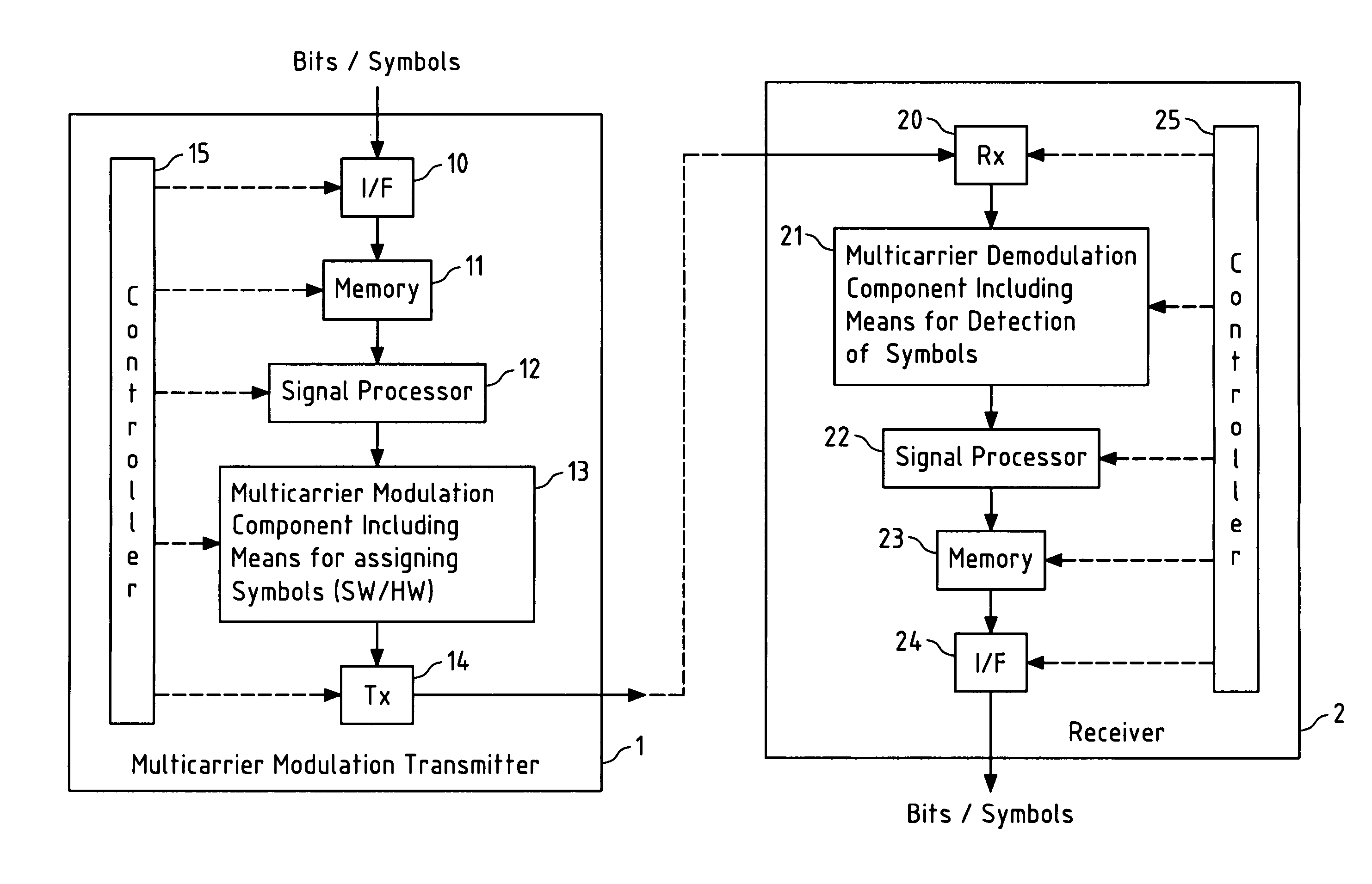
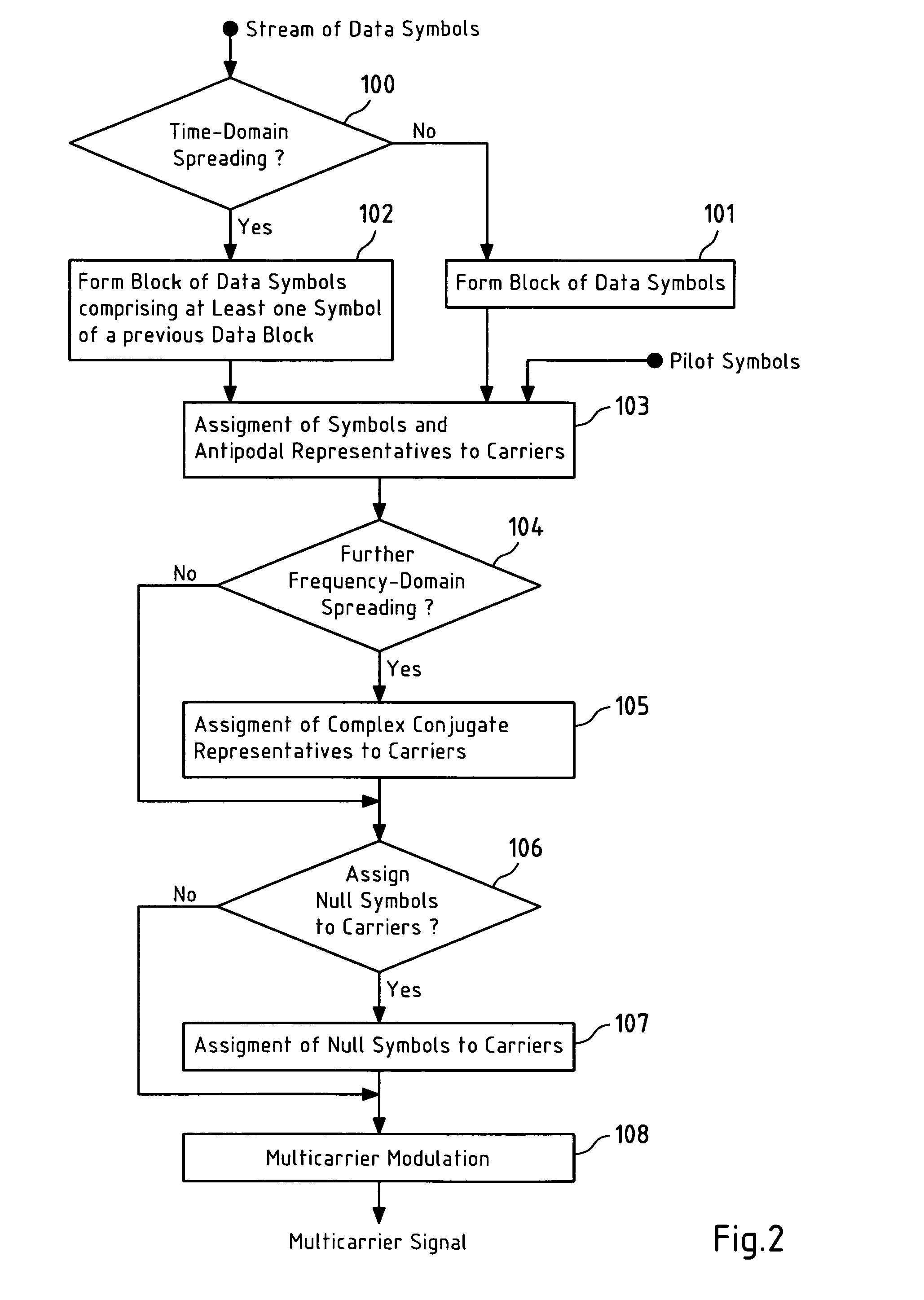
[0054] The implementation of the present example is according to FIG. 2, which depicts a flowchart of a method for mitigation of interference introduced by a multicarrier modulation according to the present invention, and wherein said flowchart describes operational steps of a multicarrier modulation component 13 including means for assigning symbols within a transmitter 1 depicted in FIG. 1.

[0055] In the present example, a stream of 50 QPSK data symbols {c0, . . . , c49} is received for every other OFDM symbol interval. In a step 100, it is checked whether time-domain spreading should be applied or not. As this is not the case in the present example, during the first OFDM symbol interval the subset S1={c0, . . . , c24} of said data sym...

second embodiment

of the Present Invention

[0077] As a second example for the application of the present invention, said MB-OFDM modulation for said 53.3 and 80 Mbps operational modes of said WPANs is considered and an embodiment of the present invention is given therefore.

[0078] The implementation of the present example is according to FIG. 1, which depicts a flowchart of a method for mitigation of interference introduced by a multicarrier modulation according to the present invention, and wherein said flowchart describes operational steps of a multicarrier modulation component 13 including means for assigning symbols within a transmitter 1 depicted in FIG. 1.

[0079] In the present example, a stream of 50 QPSK data symbols {c0, . . . , c49} is received for every other OFDM symbol interval. In a step 100, it is checked whether time-domain spreading should be applied or not. During said first OFDM symbol interval, no time-domain spreading is introduced, thus in a step 101 a data block S1={c0, . . . , ...

third embodiment

of the Present Invention

[0090] As a third for the application of the present invention, said MB-OFDM modulation for said 106.7, 160 and 200 Mbps operational modes of said WPANs is considered and an embodiment of the present invention is given therefore.

[0091] The implementation of the present example is according to FIG. 1, which depicts a flowchart of a method for mitigation of interference introduced by a multicarrier modulation according to the present invention, and wherein said flowchart describes operational steps of a multicarrier modulation component 13 including means for assigning symbols within a transmitter 1 depicted in FIG. 1.

[0092] In the present example, a stream of 100 QPSK data symbols {c0, . . . , c99} is received for every other OFDM symbol interval. In a step is checked whether time-domain spreading should be applied or not. As this is not the case in the present example, during the first OFDM symbol interval the subset S1={c0, . . . ,c49} of said data symbols...


PUM


Abstract

This invention relates to a method, a computer program, a computer program product, a transmitter and a receiver for a multicarrier modulation, wherein symbols are assigned to carriers of a set of N carriers, said method comprising assigning at least one of said symbols to a first carrier of said set of N carriers, and assigning an antipodal representative of said at least one of said symbols to a second carrier of said set of N carriers.

Description

FIELD OF THE INVENTION [0001] This invention relates to a method for multicarrier modulation, wherein symbols are assigned to carriers of a set of N carriers. BACKGROUND OF THE INVENTION [0002] The Ultra Wide Band (UWB) technology, which may be used for the physical layer for a low-power short distance (up to 10 m) radio transmission technique for high data rates, may for instance be implemented by a multicarrier modulation. Said multicarrier modulation may be represented by an Orthogonal Frequency Division Multiplexing (OFDM) modulation, a Multi Band (MB) OFDM modulation or any other multicarrier modulation. [0003] However, said multicarrier UWB system often has to coexist with at least one narrowband radio service that operates within the spectrum of said UWB system. In general, said narrowband radio system has any bandwith that is smaller than the UWB system's bandwith. Thus, said narrowband system looks like an interferer for at least one of the carriers of said multicarrier UWB...

Claims


Application Information

Patent Timeline
IPC IPC(8): H04J11/00H04B1/713H04B1/7136
CPCH04B1/71632H04B1/719H04L5/0007H04L27/261H04L5/0048H04L5/0058H04L27/2605H04L5/0046H04L27/26
Inventor GREEN, MARILYNN P.
Owner VIVO MOBILE COMM CO LTD
Learn More