
Reinforcing assembly, and reinforced concrete structures using such assembly

a technology of reinforcement and assembly, applied in the direction of girders, building repairs, joists, etc., can solve the problems of deficient current state-the-art systems for punching shear reinforcement in slabs, prior art structures providing nothing to reduce or neutralize the horizontal component of diagonal tension, etc., to achieve greater protection of punching shear reinforcemen

Inactive Publication Date: 2012-07-17
MARTTER RICHARD P
View PDF22 Cites 5 Cited by
  • Summary
  • Abstract
  • Description
  • Claims
  • Application Information

AI Technical Summary

Benefits of technology

[0011]The diagonal working members are located perpendicular to the zone of nascent diagonal cracking and thus provide significantly greater punching shear reinforcement protection. In particular, the tensile reinforcement provided by the reinforcing assembly aligns in parallel with the stresses it is intended to resist. The ribbed characteristic of each diagonal working member provides maximum surface area for concrete bonding and provide mechanical interlock for the transfer of concrete stresses to the rebar, and the spacing of the working members preferably is such that the members are closer together near the column (where stresses are highest), while transitioning to a progressively wider spacing away from the column where stresses are lower. Further, the preferably small diameter of the rebar provides maximum surface area for bonding interaction per unit weight of rebar.

Problems solved by technology

The inventor has recognized that current state-of-the-art systems for punching shear reinforcing in slabs are deficient in that they are designed primarily with smooth vertical members that do not provide protection against shear stress in an area of the slab where shear cracks originate, namely, the central zone of the slab.
In the central zone of the slab thickness, however, prior art structures provide nothing to reduce or neutralize the horizontal component of the diagonal tension.

Method used


Image

  • Reinforcing assembly, and reinforced concrete structures using such assembly
  • Reinforcing assembly, and reinforced concrete structures using such assembly
  • Reinforcing assembly, and reinforced concrete structures using such assembly

Examples


Embodiment Construction

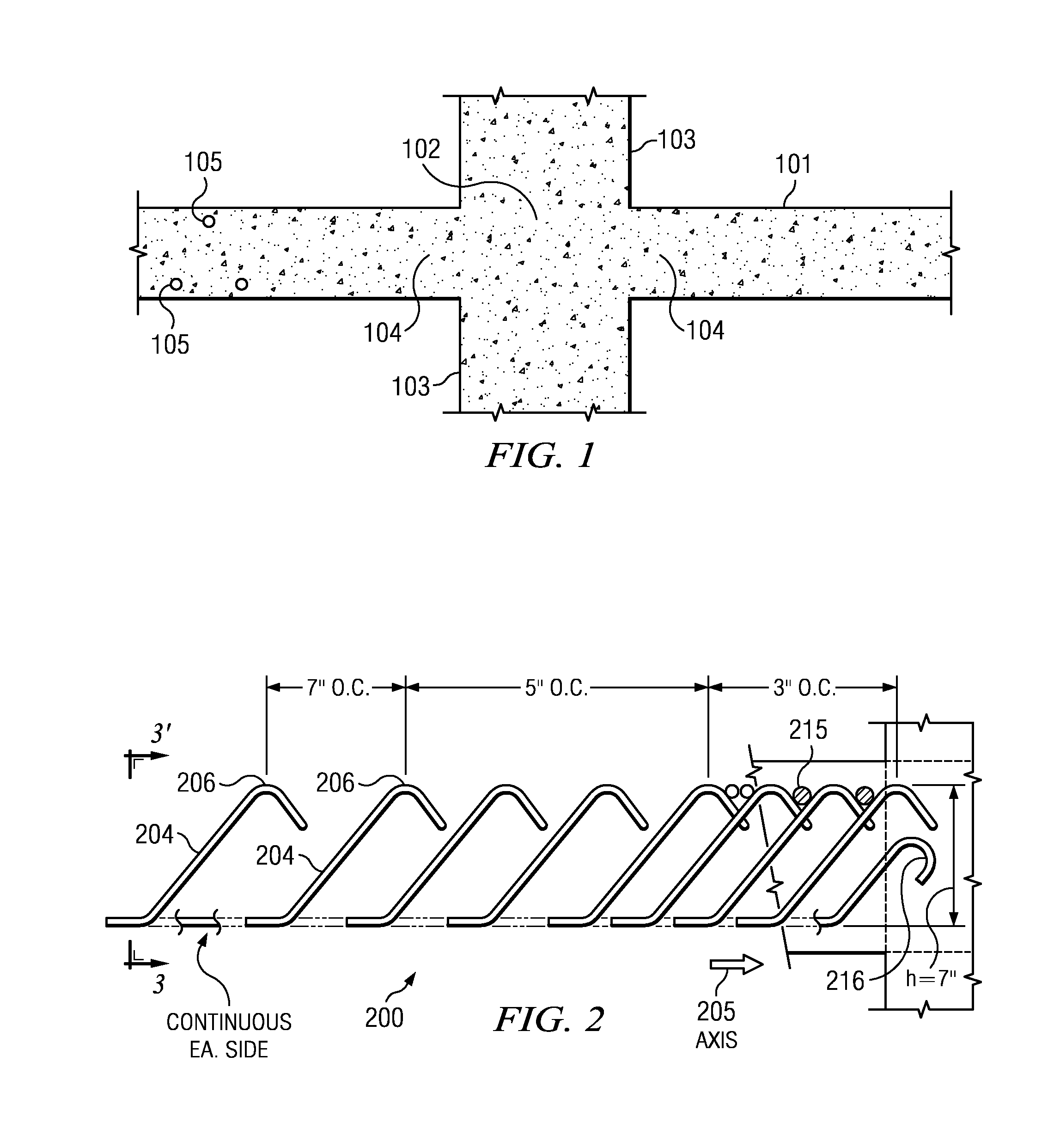
[0019]FIG. 1 is a cross-sectional view of a concrete slab structure at an area surrounding the intersection of the slab structure with a supporting column showing undesirable cracking caused by punching shear forces. The column may be a steel supporting column, a concrete supporting column, or the like. In this example, a concrete slab 101 is attached to a support column 103. The concrete slab typically includes internal structural components that provide reinforcement. These include reinforcing bar (or “rebar”), which typically is formed of carbon steel and used in reinforced concrete and masonry structures. In a typical embodiment, rebar 105 extends across the top of the slab (into and out of the view as shown), as well as across the bottom of the slab (although rebar in the bottom is not always used). Reference numeral 102 represents a load or “reaction” area; punching shear failure causes cracks, particular in areas of high stress, such as indicated by reference numerals 104.

[00...


PUM


Abstract

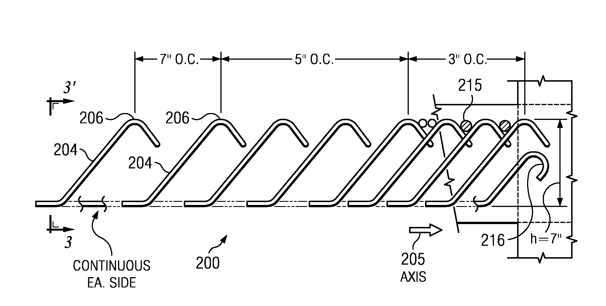
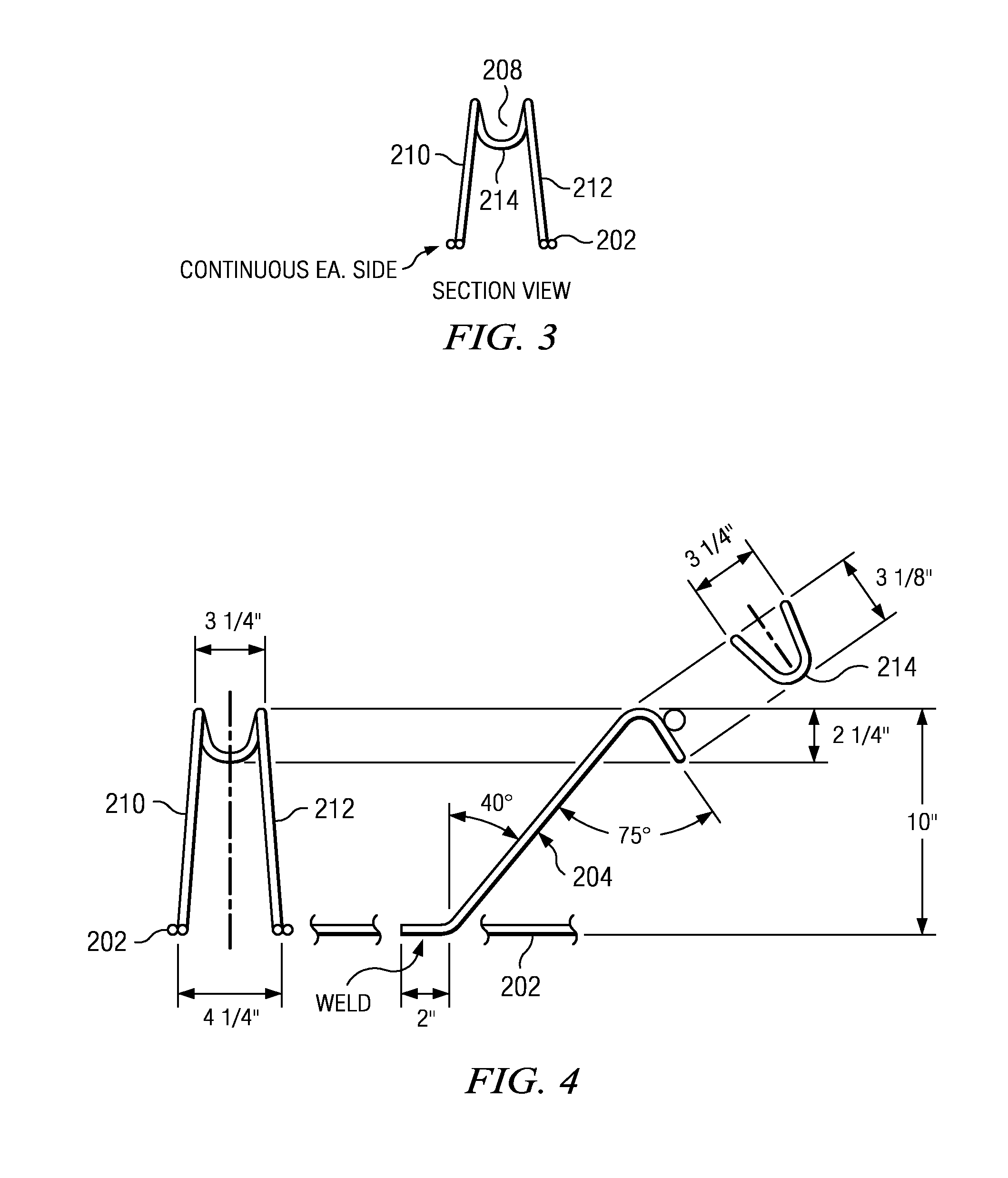
A reinforcing assembly to address this problem comprises a plurality of diagonal working members (preferably formed of #3 rebar) each of which is “ribbed” to provide increased surface area for bonding to the concrete, and each of which is attached to a horizontal runner independently such that the diagonal working members are variably spaced along the assembly. Relative to the horizontal runner, each diagonal member is “bent” at a given angle, preferably in the range of 45° plus or minus 25°. The reinforcing assembly is designed for use to provide punching shear reinforcement in a reinforced concrete structure such as, without limitation, a slab (in which the assembly is supported) located adjacent a structural column. The top of each diagonal member in the reinforcing assembly preferably comprises a double hook that is configured to fit within reinforcing bars that run along the top of the slab. The horizontal runner comprises a pair of spaced-apart, longitudinally-extending carrier (or “support”) bars, each of which preferably terminates on one end (namely, at the support column) at one end in a structure that is bent upwards and hooked. Preferably, the hooked structure of each runner bar extends into the structural column to provide additional reinforcement, thereby converting the runner bar into a reinforcing member that provides the same function as the other diagonal members, and at a confined location at a highest point of stress (i.e. where the slab attaches to the column) where it would not be possible otherwise to fit a diagonal member.

Description

BACKGROUND[0001]1. Technical Field[0002]This disclosure relates generally to reinforcing assemblies for use in structural concrete members.[0003]2. Background of the Related Art[0004]Commercial concrete is a mixture of cement, sand and stone aggregate held together in a rigid structure by the addition of water. So-called “unreinforced” concrete has fairly good resistance to compressive stresses, however, any significant tension tends to break the structure and cause undesirable cracking and separation. To address this problem, concrete is typically “reinforced” by embedding in place (within the rigid structure) a solid member made of a material with high strength in tension. Reinforced concrete structures are available commercially in many shapes and sizes, such as slabs, beams, footings and flat foundations.[0005]Commercial and industrial structural concrete members, even when made with reinforced concrete, are highly susceptible to shear forces that create diagonal tensile forces ...

Claims


Application Information

Patent Timeline
Patent Type & Authority Patents(United States)
IPC IPC(8): E04H12/00
CPCE04C5/0645
Inventor MARTTER, RICHARD P.
Owner MARTTER RICHARD P
Learn More