Method for guiding a medical device

a medical device and image guidance technology, applied in the field of tissue ablative energy treatment of patients, can solve the problems of coagulative necrosis, complex surgical maze procedure, and tissue damage, and achieve the effect of facilitating position, manipulation, stabilizing and/or holding an organ

Inactive Publication Date: 2012-07-17
MEDTRONIC INC
View PDF424 Cites 675 Cited by
  • Summary
  • Abstract
  • Description
  • Claims
  • Application Information

AI Technical Summary

Benefits of technology

[0024]It is still another object of the present invention to have an organ positioning system and method that comprises a device that engages organ tissue and allows a surgeon to easily position, manipulate, stabilize and / or hold an organ during a guided or navigated ablation procedure.
[0027]Another object of the present invention is to have an organ positioning system and method that comprises a device that engages organ tissue and allows a surgeon to easily position, manipulate, stabilize and / or hold an organ during a controlled intermittent asystole, guided or navigated ablation procedure.
[0028]Some of the advantages of the present invention are that varying intensity levels of ablating energy can be delivered to tissue for varying periods of time depending on desired ablative effect, the duration of ablating energy delivery or application to the tissue needed to accomplish a desired effect may be relatively brief depending on desired size for the lesions of the ablated tissue area and / or desired thermal effect on the tissue, the ablating member used to deliver the ablating energy may be stationary or may be movable, or may be a microprocessor-controlled phased array in order to scan a target area with ablating energy, a plurality of individual ablated tissue areas can be formed in the tissue with the ablated tissue areas being separate and discontinuous or being contacting, abutting, contiguous or overlapping to form a single continuous ablated tissue area of desired size and / or shape, the ablating member can remain stationary or can be moved along to scan a target area with ablating energy, the ablating member may be designed with a focusing configuration designed to ensure that the lesions of the ablated tissue area have a desired cross-sectional size, begin a desired depth within the tissue and have a desired depth, the ablating member may be positioned externally adjacent or in contact with an external surface of the tissue or may be acoustically coupled with the tissue to form an internal ablated tissue area without damaging the tissue surface and, in particular, a body cavity such as the esophagus or trachea, and an ablated tissue area of definitive size can be repeatedly and consistently produced. The esophagus is close to the posterior of the left atrium of the heart. This position makes it particularly attractive for trans-esophageal echocardiography (TEE) imaging as well as trans-esophageal ultrasound ablation.
[0031]An ablating member may have a focusing configuration that causes the ablting energy to be focused a predetermined distance from an active face of the abalting member. Also, the focusing configuration results in formation of lesions of predetermined or known depth in accordance with the length of the focusing zones, the selected ablating energy intensities and frequencies and the selected duration times for ablating energy delivery. The lesion depths are selected so that the lesions do not extend deeper than desired, thereby avoiding unwanted damage to surrounding tissue. The plurality of lesions may be non-contacting, with each lesion surrounded by unablated tissue. One or more of the plurality of lesions may contact another one of the plurality of lesions. The cross-sectional size of the lesions and the location and arrangement of the focusing zones in the tissue result in formation of a specific size ablated tissue area having a specific cross-sectional configuration. A single, discrete ablated tissue area or a plurality of single, discrete ablated tissue areas can be formed in the tissue in a single procedure or treatment performed at one time or in multiple procedures or treatments performed at different times. Where a plurality of ablated tissue areas are formed, the ablated tissue areas can be contiguous, contacting, overlapping or in abutment with one another so that the ablated tissue areas together form or create a single ablated tissue area of larger cross-sectional size and / or of a desired cross-sectional configuration.

Problems solved by technology

Thermal effects include heating of the tissue; and, when the tissue is heated to a sufficiently high temperature, tissue damage such as coagulative necrosis can be produced.
Occasionally, these electrical signals do not function properly, thereby causing heart arrhythmias.
Although successful in treating AF, the surgical Maze procedure is quite complex and is currently performed by a limited number of highly skilled cardiac surgeons in conjunction with other open-heart procedures.
Irrigated RF epicardial ablation approaches allow the heat to penetrate deeper into the tissue, but tend to be limited in depth.
Without sufficient space and field of view, it is difficult for the surgeon to recognize the anatomical location and identity of structures viewed on the video display.
The requirement for space surrounding the working field has the effect of limiting the regions which can be safely and confidently accessed by minimally invasive endoscopic techniques.
For example, it is very difficult for the surgeon to endoscopically visualize the passage of instruments through the spaces posterior to and around portions of the heart such as the transverse and oblique sinuses.
Due to these limitations, some procedures have not been attempted using minimally invasive endoscopic techniques.

Method used


Image

  • Method for guiding a medical device
  • Method for guiding a medical device
  • Method for guiding a medical device

Examples


Embodiment Construction

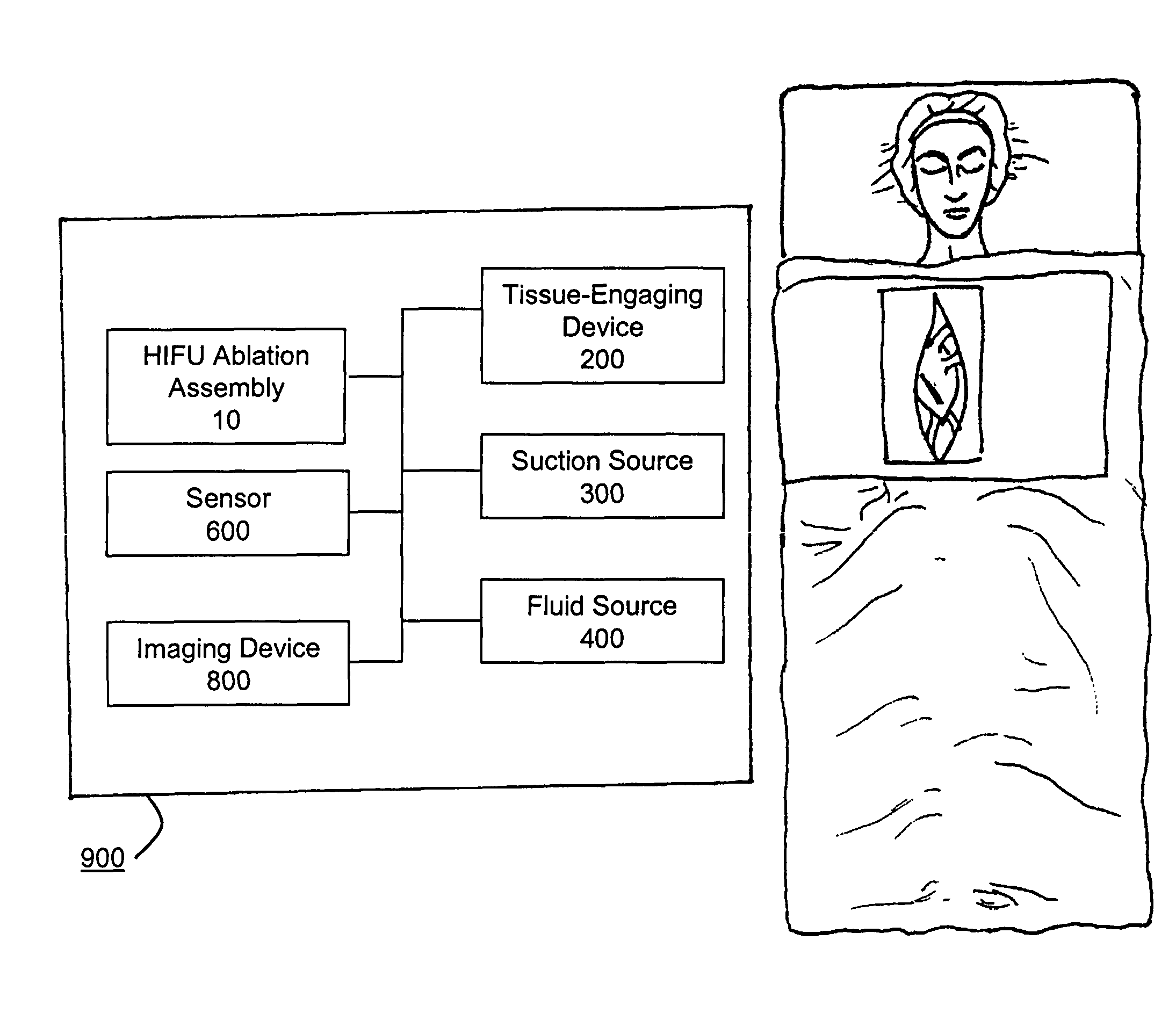
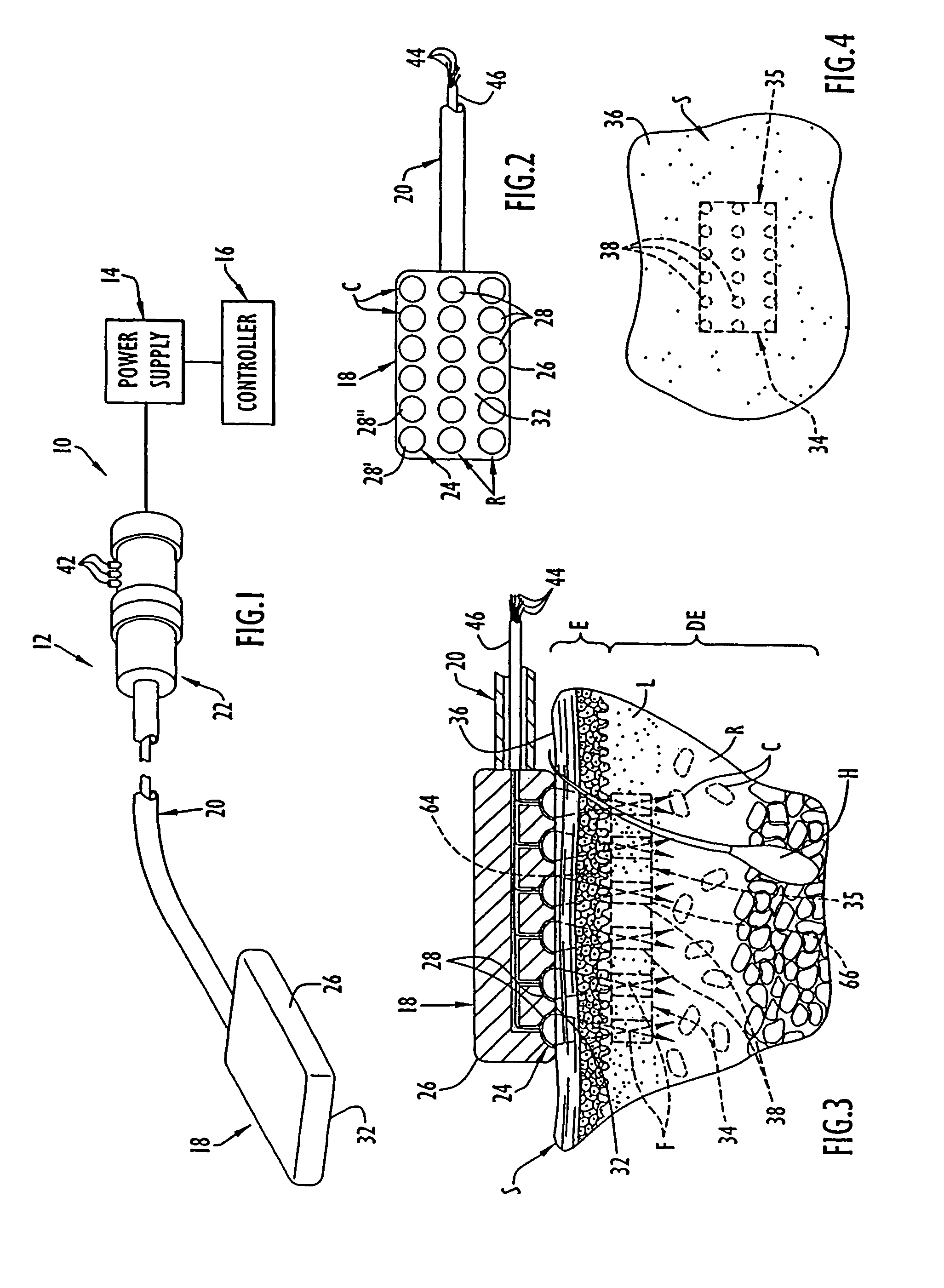
[0060]One embodiment of an ablation or stimulation assembly or system 10 for use in the methods of the present invention is illustrated in FIG. 1 and is similar to the HIFU stimulation assembly described in prior U.S. patent application Ser. No. 10 / 464,213 and U.S. patent application Ser. No. 10 / 600,871, the disclosures of which are incorporated herein by reference. The high intensity focused ultrasound ablation or stimulation assembly or system 10 includes a focused ultrasound ablation or stimulation device 12, a power supply 14 and a controller 16. The focused ultrasound ablation or stimulation device 12 is similar to that described in U.S. patent applications Ser. Nos. 10 / 464,213 and 10 / 600,871 and includes a focused ultrasound emitting member 18, an elongate handle shaft or body 20 having a distal end at which the ultrasound emitting member is disposed and a handle or handpiece 22 coupled to a proximal end of the handle shaft 20. As shown in FIGS. 2 and 3, the ultrasound emittin...


PUM


Abstract

A device and method for ablating tissue is disclosed comprising the steps of acquiring an anatomical image of a patient, correlating the image to the patient, guiding an ablating member within the patient while tracking the position of the ablating member in the patient, positioning the ablating member in a desired position to ablate tissue, emitting ablating energy from the ablating member to form an ablated tissue area and removing the ablating member from the patient.

Description

CROSS-REFERENCE TO RELATED PATENT APPLICATIONS[0001]This application is a continuation-in-part of U.S. patent application Ser. No. 11 / 128,686 filed May 13, 2005, now U.S. Pat. No. 7,706,882, which claims the benefit of U.S. Provisional Patent Application Ser. No. 60 / 571,182 filed on May 14, 2004, the disclosures of which are incorporated herein by reference in their entirety.[0002]U.S. patent application Ser. No. 11 / 128,686 filed May 13, 2005 is a continuation-in-part of U.S. patent application Ser. No. 10 / 464,213 filed Jun. 18, 2003 now U.S. Pat. No. 6,936,046, which is a continuation of U.S. patent application Ser. No. 09 / 629,194 filed Jul. 31, 2000, now U.S. Pat. No. 6,595,934, which is a continuation-in-part of U.S. patent application Ser. No. 09 / 487,705 filed Jan. 19, 2000, now abandoned, the disclosures of which are incorporated herein by reference in their entirety.[0003]U.S. patent application Ser. No. 11 / 128,686 filed May 13, 2005 is also a continuation-in-part of U.S. pate...

Claims


Application Information

Patent Timeline
Patent Type & Authority Patents(United States)
IPC IPC(8): A61B18/04A61B18/08
CPCA61B19/5244A61N7/02A61B18/1442A61B2017/00243A61B2018/00291A61B2019/5251A61B2019/5253A61B2019/5263A61B2019/5276A61B2019/547A61N7/022A61N2007/0078A61B8/4272A61B2034/2053A61B2034/2063A61B34/20A61B2034/2051A61B2090/378A61B2090/397
Inventor FRANCISCHELLI, DAVID E.HISSONG, JAMES B.KEOGH, JAMES R.SKARDA, JAMES R.STEWART, MARK T.
Owner MEDTRONIC INC
Why Eureka
Try Eureka