Toner transferring mechanism, developing apparatus and image forming apparatus therewith
a technology of developing apparatus and toner, which is applied in the field of toner transferring mechanism, can solve the problems of poor image formation on paper, toner being stuck, and the flue of the toner inside the housing, and achieves satisfactory toner transfer performance and high reliability
- Summary
- Abstract
- Description
- Claims
- Application Information
AI Technical Summary
Benefits of technology
Problems solved by technology
Method used
Image

Examples
first embodiment
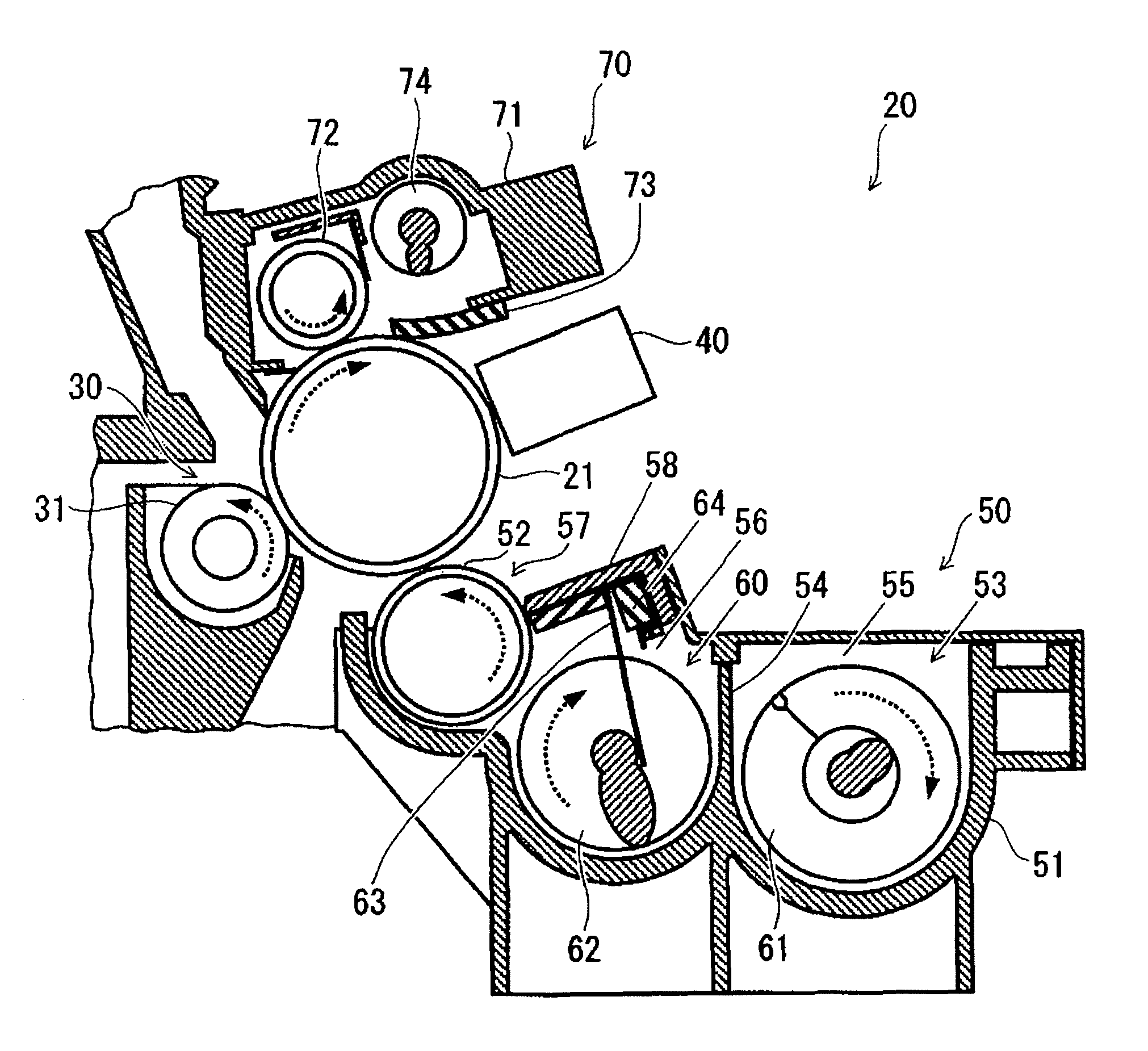
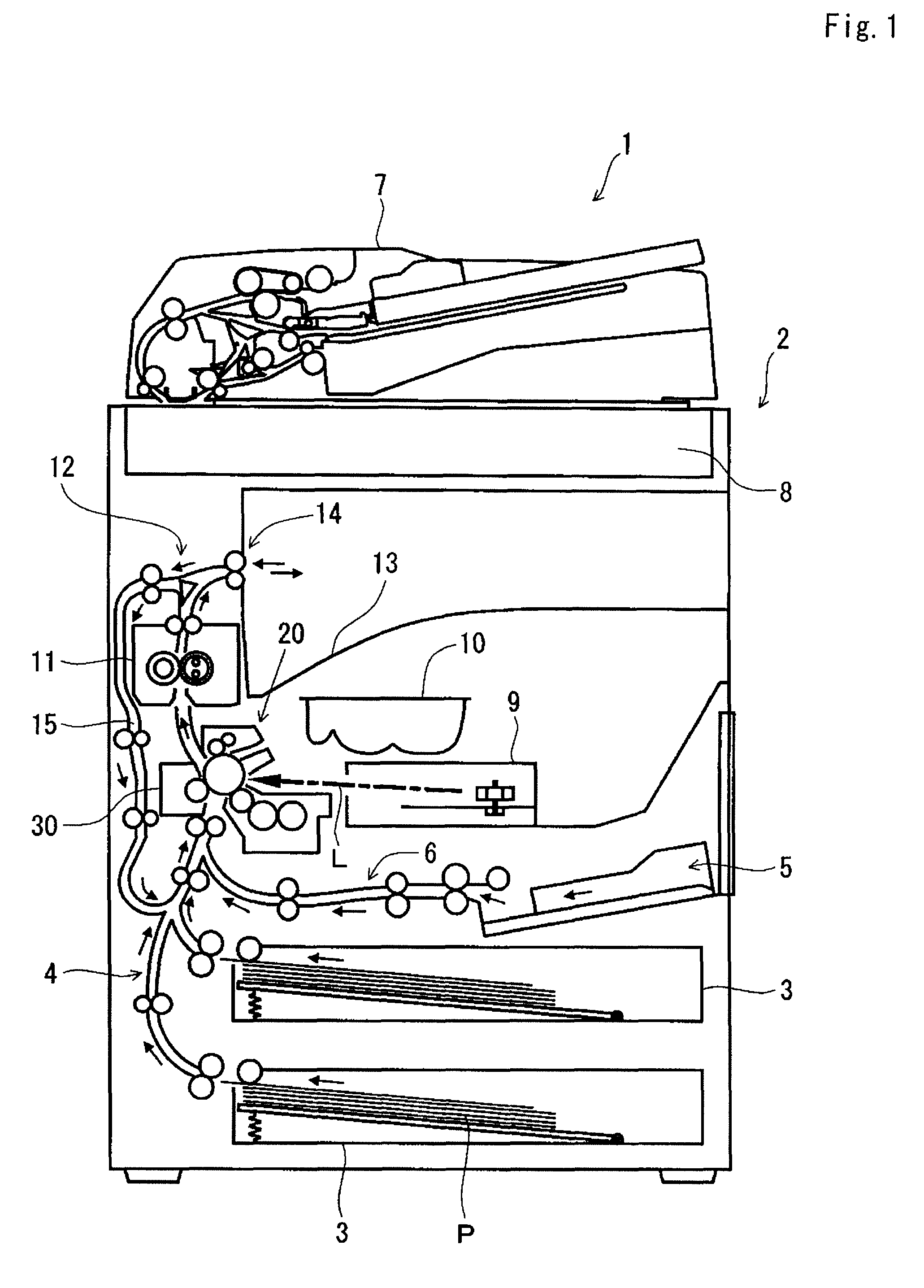
[0038]First, in respect of an image forming apparatus provided with a toner transferring mechanism according to the present invention, an outline of its construction will be described, with reference to FIG. 1, with the focus on an image outputting operation. FIG. 1 is a vertical sectional front view schematically showing an image forming apparatus. In FIG. 1, arrowed solid lines represent sheet conveyance passages and directions, and an arrowed dash-dot line represents a laser beam L.
[0039]As shown in FIG. 1, sheet feeding cassettes 3 serving as sheet feeding sections are disposed at the bottom inside a main body 2 of an image forming apparatus 1. The sheet feeding cassettes 3 each accommodate sheets of paper P, such as unprinted cut sheets of paper, in the form of a stack. The sheets of paper P are separated and fed, one after another, in a left-upward direction of the sheet feeding cassettes 3 in FIG. 1. The sheet feeding cassettes 3 can be horizontally pulled out from the front ...
second embodiment
[0074]A toner transferring mechanism is provided with a plurality of scraping members 65 as shown in FIG. 6. The scraping member 65 is provided with a plurality of holding portions 65a being held in the housing 51 with the holding member 64 and a contact portion 65b making contact with the blade portion 62a of the second agitating and transferring member 62, and in addition, the scraping member 65 is provided with a load absorbing portion 65c between these portions 65a and 65b. The load absorbing portion 65c is formed into a coil, and can be elastically deformed preceding the other portions such as the holding portions 65a and the contact portion 65b.
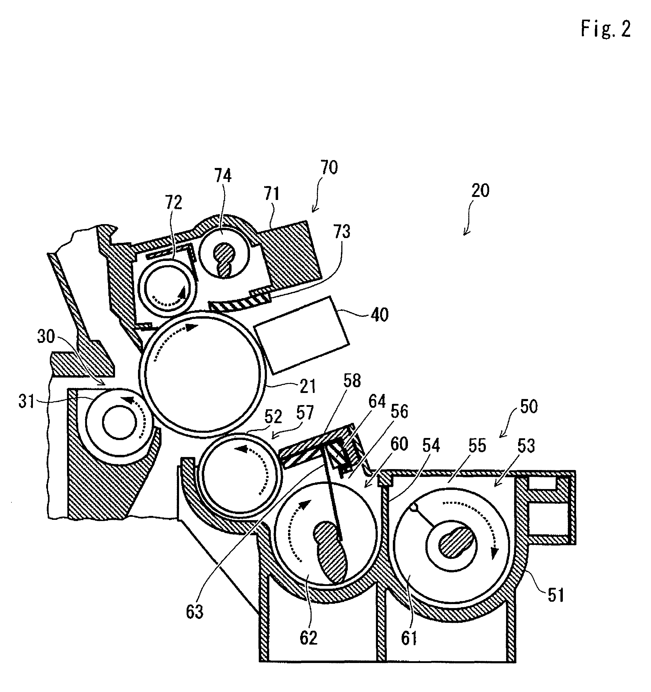
[0075]As the second agitating and transferring member 62 rotates, the blade portion 62a rotates so as to transfer toner, as described earlier, to the near side of FIG. 2, namely in the direction indicated by arrow A in FIG. 3. Meanwhile, since the scraping members 65 are disposed at the interval Pb which is different from and smaller ...
fifth embodiment
[0085]A toner transferring mechanism is provided with a plurality of scraping members 68 as shown in FIGS. 9 and 10. The scraping members 68 are arranged at a regular interval in the axial direction of the second agitating and transferring member 62. The scraping members 68 adjacent to each other form an interval Pb which is approximate to a spiral pitch Pa of the blade portion 62a of the second agitating and transferring member 62, and which is smaller than the spiral pitch Pa.
[0086]Moreover, the scraping members are composed of a sheet-like member as shown in FIG. 10. The scraping members 68 are formed integrally with a holding portion 68a being held in the housing 51 with the holding member 64, and are each provided with a contact portion 68b making contact with the blade portion 62a of the second agitating and transferring member 62, and a load absorbing portion 68c between these portions 68a and 68b. The load absorbing portion 68c is formed by providing an opening 68d in the s...
PUM
 Abstract
Description
Claims
Application Information
 - R&D
- Intellectual Property
- Life Sciences
- Materials
- Tech Scout
- Unparalleled Data Quality
- Higher Quality Content
- 60% Fewer Hallucinations
Browse by: Latest US Patents, China's latest patents, Technical Efficacy Thesaurus, Application Domain, Technology Topic, Popular Technical Reports.
© 2025 PatSnap. All rights reserved.Legal|Privacy policy|Modern Slavery Act Transparency Statement|Sitemap|About US| Contact US: help@patsnap.com