Ascender device with cam for belaying on a fixed rope

a technology of fixed rope and ascender device, which is applied in the direction of life-saving devices, sports apparatus, climbing, etc., can solve the problems of complicated apparatus to achieve, and achieve the effect of convenient use, convenient fitting and convenient handling

a technology of fixed rope and ascender device, which is applied in the direction of life-saving devices, sports apparatus, climbing, etc., can solve the problems of complicated apparatus to achieve, and achieve the effect of convenient use, convenient fitting and convenient handling

US8225905B2Active Publication Date: 2012-07-24ZEDEL CORP

Image

  • Ascender device with cam for belaying on a fixed rope
  • Ascender device with cam for belaying on a fixed rope
  • Ascender device with cam for belaying on a fixed rope

Examples


Embodiment Construction

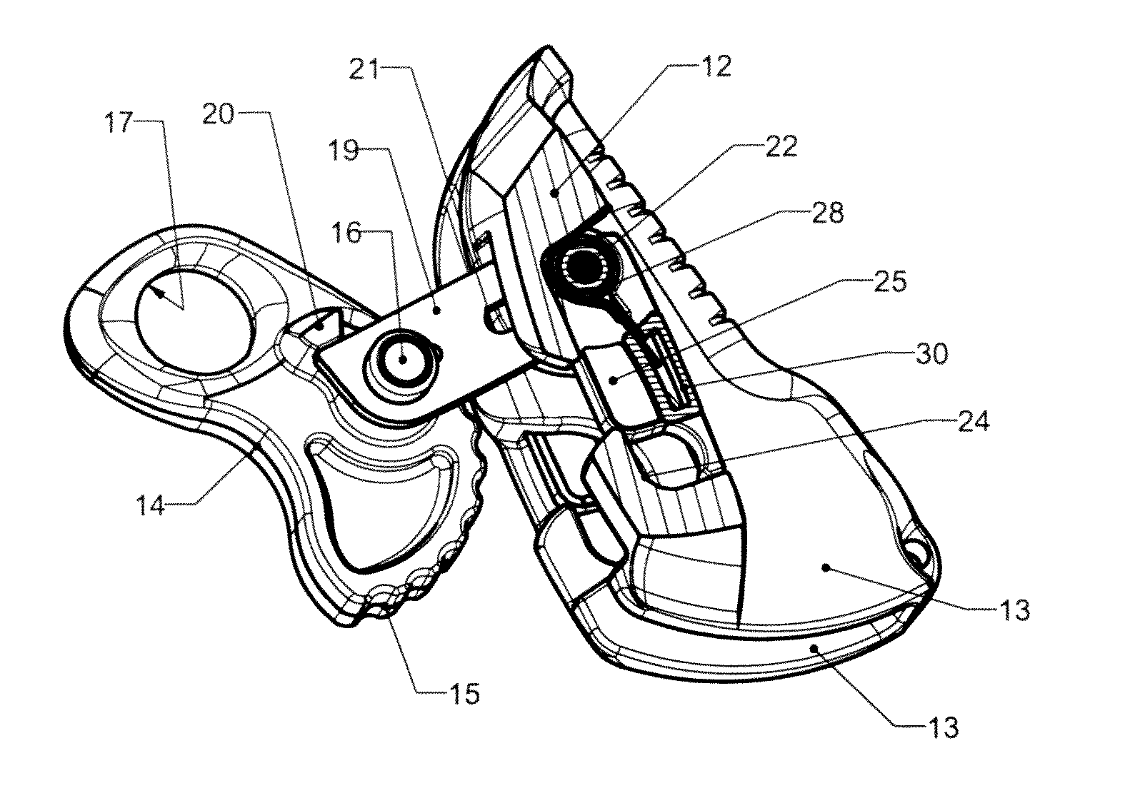
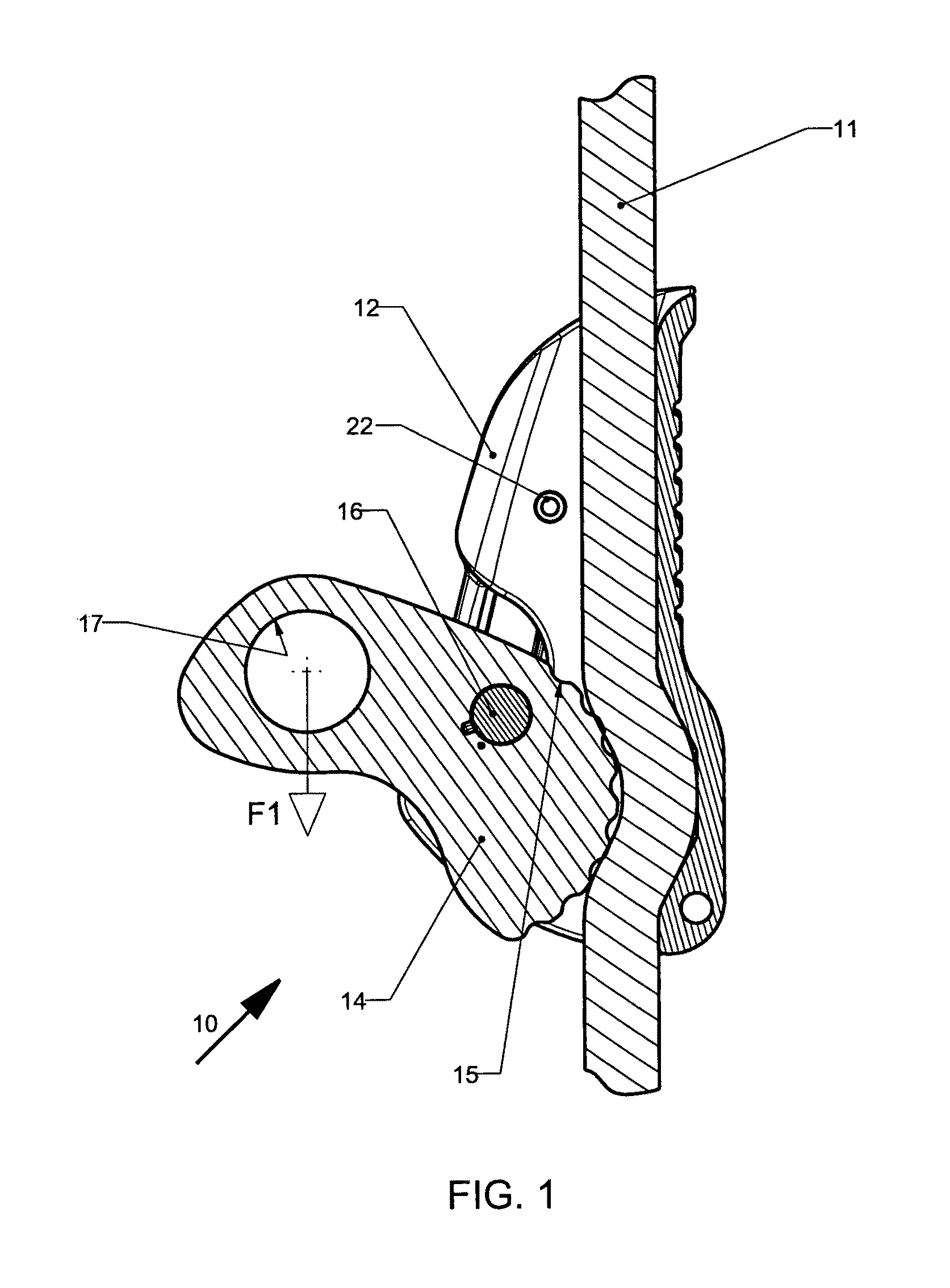
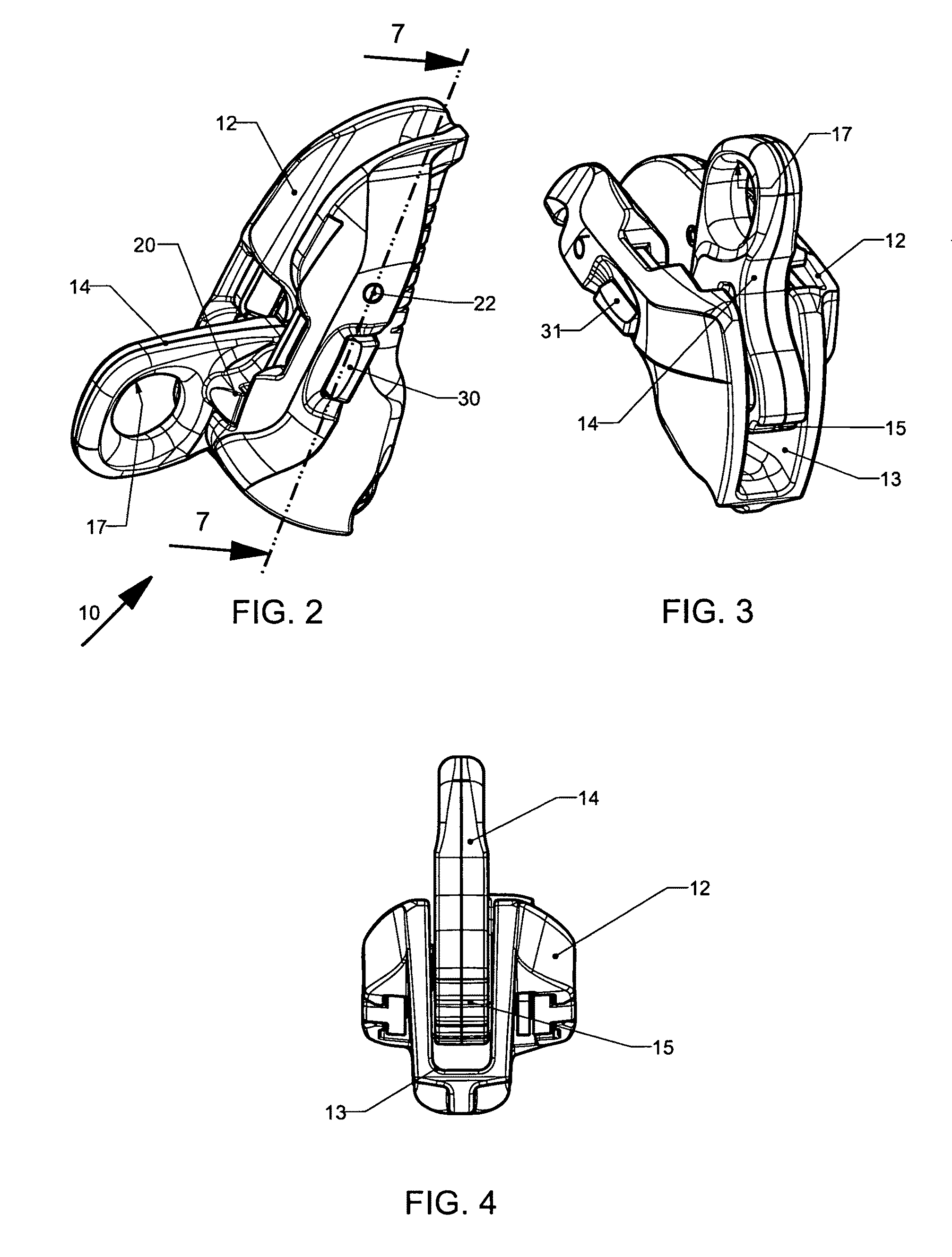
[0025]With reference to FIGS. 1 to 9, an ascender device 10 is used in climbing for belaying a climber along a fixed rope 11. It comprises a metal body 12 provided with a central trough 13 for passage of the rope 11, and an actuating lever 14 with a locking cam 15.

[0026]Actuating lever 14 can swivel around a transverse pivot 16 between a first clamping position (FIGS. 1 and 8) and a second releasing position of rope 11 (FIG. 9). Cam 15 extends up to the inside end of actuating lever 14 facing the bottom of trough 13 so as to clamp rope 11 in the first position. At the opposite end of cam 15, actuating lever 14 is provided with a circular hole 17 accessible from the outside for attaching a safety means designed to be connected to the climber's harness.

[0027]The safety means can be a carabiner, a cord or a strap. The surface of cam 15 coming into contact with rope 11 comprises a plurality of ribs or raised dots.

[0028]After rope 11 has been inserted in trough 13, ascender device 10 all...


PUM


Abstract

An ascender device for belaying on a fixed rope, comprising a body with a trough, and an actuating lever having a pivot, a cam for clamping the rope, and a hole for attaching a safety means. A connecting arm with a button-hole is articulated between the pivot and body to move the actuating lever between an inactive position facilitating insertion of the rope in the trough and an active position wherein the ends of the pivot are housed in aligned recesses acting as bearings. A double lock comprises a first lock and a second lock to secure the two opposite ends of the pivot in the recesses, each lock being associated with an unlocking tab for releasing same.

Description

BACKGROUND OF THE INVENTION[0001]The invention relates to an ascender device for belaying on a fixed rope comprising a body with a trough for the rope to pass through, and an actuating lever having a pivot, a cam for clamping the rope, and a hole for attaching a safety means.[0002]Such an ascender is designed for secured progression on a fixed rope and for constituting hauling or hoisting systems.STATE OF THE ART[0003]An ascender known under the trade-name Microcender from PETZL (registered trademark) comprises a U-shaped clamp forming a trough, a lever with a locking cam, and a removable pin enabling the ascender to be fitted or removed at any point of the rope. The lever and pin remain connected to the body of the ascender via a flexible link to make them captive after the pin has been removed.[0004]The document EP 678310 relates to a fall arrest device able to be automatically locked onto a safety rope. It comprises:[0005]a body with a trough for passage of the rope,[0006]an actu...

Claims


Application Information

Patent Timeline
24 Jul 2012
Publication
US8225905B2
IPC
A62B1/12
CPC
A62B1/14
Inventors
DELAITTRE, ARNAUD; MAURICE, ALAIN