LED light source utilizing magnetic attachment

a technology of led light source and magnetic attachment, which is applied in the direction of instruments, lighting support devices, and semiconductor/solid-state device details, etc., can solve the problems of generating significant amounts of heat, presenting significant challenges, and unacceptably reducing the efficiency or lifetime of leds

Active Publication Date: 2012-07-24
BRIDGELUX INC
View PDF15 Cites 21 Cited by
  • Summary
  • Abstract
  • Description
  • Claims
  • Application Information

AI Technical Summary

Problems solved by technology

LED sources that are to replace conventional lighting generate significant amounts of heat that must be transferred to the environment without raising the operating temperature of the LEDs to levels that unacceptably decrease the efficiency or lifetime of the LEDs.
To move this amount of heat from the LEDs without increasing the LED temperature to an unacceptable level presents design challenges and is the subject of numerous patents.
In situations in which an existing luminaire is being upgraded by replacing a conventional light source such as a number of fluorescent tubes with an LED-based light source, the problems associated with mounting the replacement light source that includes the heat-conducting structure to the final heat-dissipating structure can present significant challenges.
If the replacement light source matches the form factor of the conventional light source that is being replaced, the area that is available for the heat-dissipating structure is often too small to provide adequate heat transfer without incurring substantial costs to provide a large area heat-transfer surface that fits in a restricted space that was previously occupied by the conventional light source.
If the heat-dissipating structure is to be part of the existing luminaire, attachment of the heat-dissipating structure to the existing luminaire can present significant challenges.
This constraint limits the power output of the replacement light source and / or increases the cost by requiring a more complex heat-dissipating structure that includes fins or the like that must fit into one half of the cylindrical replacement source.
Methods that utilize adhesives or mechanical fasteners present a new set of problems.
In many cases, the existing light source cannot be conveniently removed to make these alterations, as it is attached to structural members of the building.
Hence, the alterations to the existing fixture must be made in place which incurs significant costs.
In addition, the type of fasteners that can be utilized are limited by the fact that all sides of the existing fixture cannot be conveniently accessed.
If adhesives are used, replacing the new light source when it fails can present additional problems.
Furthermore, the surfaces of many existing fixtures are painted or otherwise coated with compounds that are not necessarily good surfaces for adhesive attachment.

Method used


Image

  • LED light source utilizing magnetic attachment
  • LED light source utilizing magnetic attachment
  • LED light source utilizing magnetic attachment

Examples


Embodiment Construction

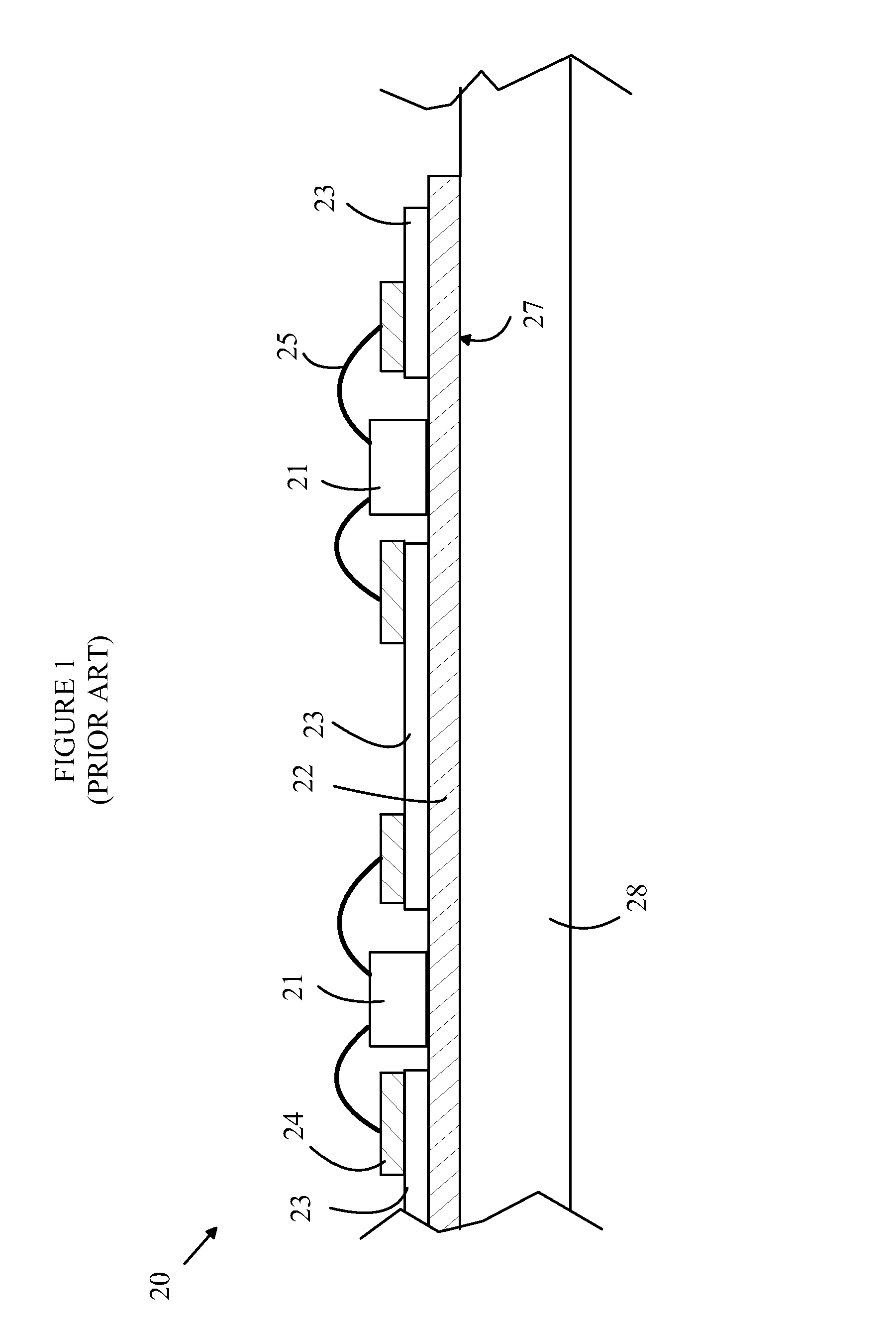
[0016]The manner in which the present invention provides its advantages can be more easily understood with reference to FIG. 1, which is a cross-sectional view of a portion of a prior art LED-based light source. Light source 20 includes a plurality of LEDs 21 that are mounted on a heat-conducting substrate 22 such as a layer of metal that is part of a printed circuit board. Substrate 22 has an insulating layer 23 on which patterned metallic traces 24 are provided for powering the LEDs. The LEDs are connected to the traces by wire bonds such as bond 25.

[0017]Light source 20 may also include a layer of phosphor over the LEDs that converts all or part of the light from the LEDs to light having a different spectrum. For example, a layer of yellow-emitting phosphor is often used over a blue-emitting LED to create a “white” light source. To simplify the drawing, the phosphor layer has been omitted.

[0018]In applications in which light source 20 is to replace a conventional light source suc...


PUM


Abstract

A light module and method for using the same are disclosed. The light module includes a heat-conducting structure and a plurality of LEDs bonded to a heat-conducting structure. The LEDs are bonded to a first surface of the heat-conducting structure and are mounted on the heat-conducting structure such that at least 50 percent of the heat generated by the LEDs is transferred to the heat-conducting structure. The heat-conducting structure includes a ferromagnetic material and is structured such that the heat-conducting structure bonds magnetically to a heat-dissipating structure with sufficient force to support the light module during the normal operation thereof when the light source is placed against the heat-dissipating structure. The present invention can be utilized for retrofitting an existing light fixture having an enclosure that includes a ferromagnetic material and a plurality of legacy light sources.

Description

BACKGROUND OF THE INVENTION[0001]Light emitting diodes (LEDs) are an important class of solid-state devices that convert electric energy to light. Improvements in these devices have resulted in their use in light fixtures designed to replace conventional incandescent and fluorescent light sources. The LEDs have significantly longer lifetimes than both incandescent bulbs and fluorescent tubes. In addition, the efficiency of conversion of electricity to light has now reached the same levels as obtained in fluorescent light fixtures.[0002]LED sources that are to replace conventional lighting generate significant amounts of heat that must be transferred to the environment without raising the operating temperature of the LEDs to levels that unacceptably decrease the efficiency or lifetime of the LEDs. The efficiency of conversion of electricity to light in an LED decreases with increasing temperature. Similarly, the lifetime of the LED also decreases with temperature. To replace conventi...

Claims


Application Information

Patent Timeline
Patent Type & Authority Patents(United States)
IPC IPC(8): H01L27/15
CPCF21V21/096H05B33/0803F21Y2101/02F21Y2103/003H01L2224/48091H01L2224/48137H01L2224/73265F21Y2103/10F21Y2115/10H05B45/345H05B45/3578H01L2924/00014
Inventor WARD, CALVIN B.
Owner BRIDGELUX INC
Why Eureka
Try Eureka