Reproduction apparatus and system

a technology of a reproduction apparatus and a system, applied in the field of reproduction apparatus, can solve the problems of not being able to view an analog terrestrial television broadcast of another channel, complicated operation, etc., and achieve the effect of preventing defects and improving usability

Inactive Publication Date: 2012-07-31
GK BRIDGE 1
View PDF6 Cites 138 Cited by
  • Summary
  • Abstract
  • Description
  • Claims
  • Application Information

AI Technical Summary

Benefits of technology

[0019]As described above, according to the reproduction apparatus of the present invention, the input of the first apparatus automatically switches to an output from the second apparatus when the output of the reproduced video or audio ends or when the output of the utility screen ends. This eliminates the necessity to perform a complicated operation of switching the input of the first apparatus, and thus results in improved usability. What is more, since such switching is performed only in the case where the manufacturer of the second apparatus is a predetermined manufacturer, it is possible to prevent the occurrence of defects that are caused by the difference in manufacturers.

Problems solved by technology

On the other hand, there is a drawback in that operations become complicated since it is necessary to manually switch inputs.
However, in the case where the recording of an analog terrestrial television broadcast is carried out, for example, when the input of the television is set to the VTR, it is not possible to view an analog terrestrial television broadcast of another channel.

Method used


Image

  • Reproduction apparatus and system
  • Reproduction apparatus and system
  • Reproduction apparatus and system

Examples


first embodiment

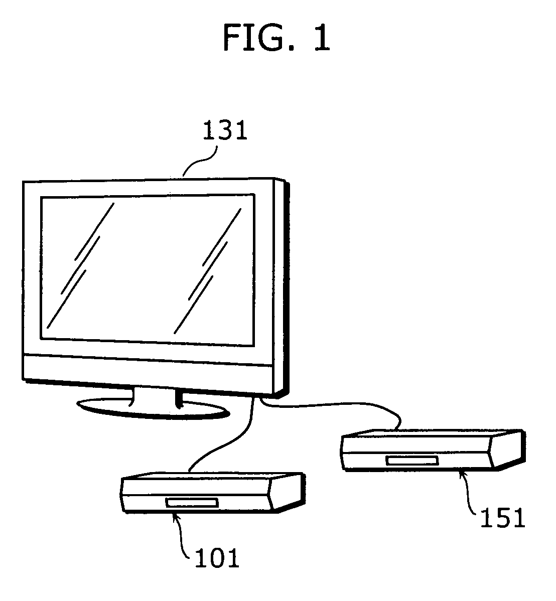
[0075]FIG. 1 is a diagram which shows an overview of the first embodiment. Here, a state in which a DVD recorder 101 and an STB 151 are connected to a television 131 is shown. The DVD recorder 101 is one example of the reproduction apparatus of the present invention, the television 131 is one example of the first apparatus of the present invention, and the STB 151 is one example of the second apparatus of the present invention. The second apparatus is not limited to a broadcast receiver such as an STB, and thus any apparatus may be used as long as such apparatus is capable of outputting video / audio data.

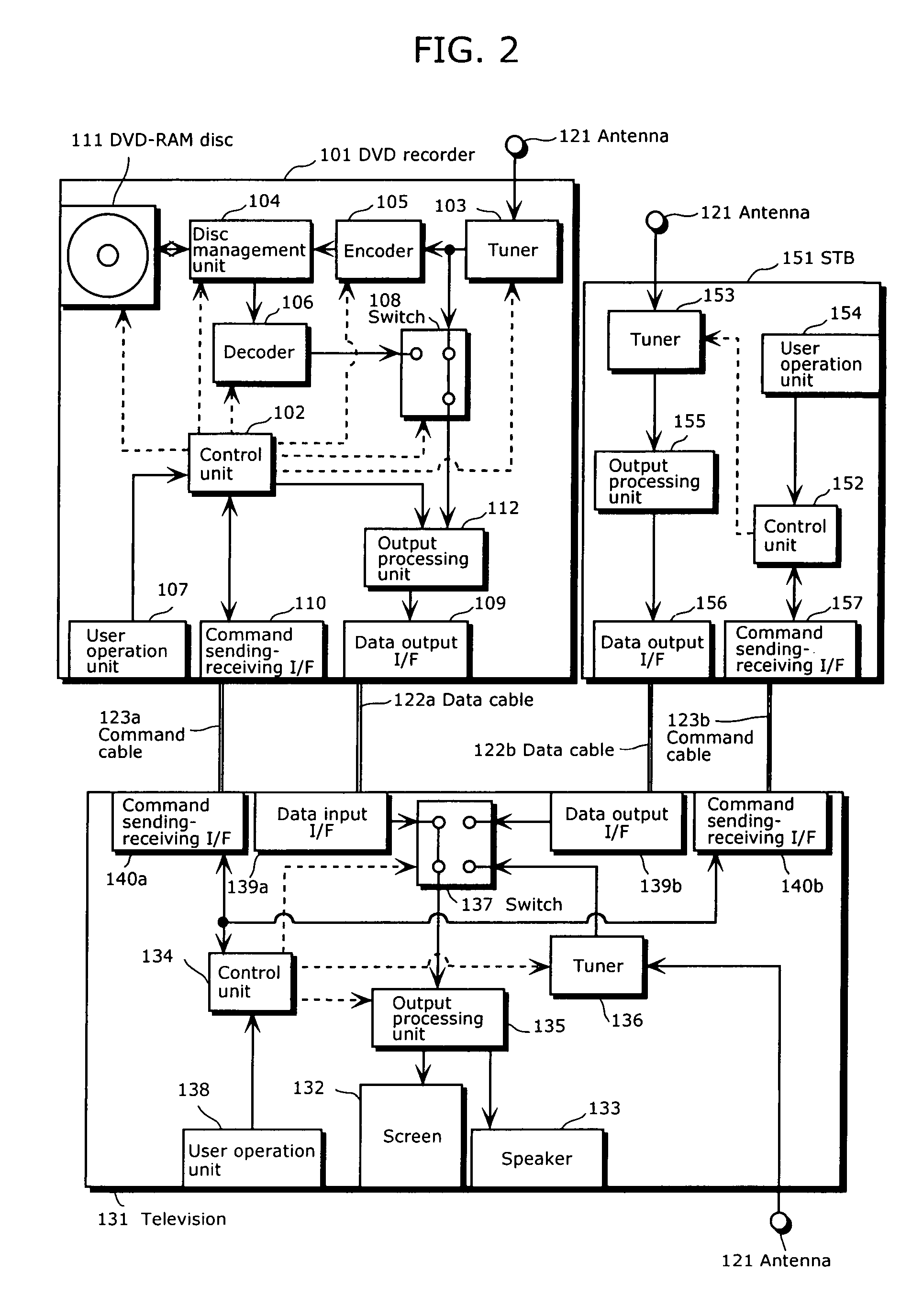
[0076]FIG. 2 is a diagram which shows example structures of the television 131, the DVD recorder 101, and the STB 151.

[0077]The DVD recorder 101 includes a control unit 102, a tuner 103, a disc management unit 104, an encoder 105, a decoder 106, a user operation unit 107, a switch 108, a data output I / F 109, a command sending-receiving I / F 110, a DVD-RAM disc 111, an output processin...

second embodiment

[0150]In the above-described first embodiment, a start output instruction command is sent to the STB at a predetermined timing at all times, but there exist STBs from various manufacturers. Thus, since there may be the case where some STBs cannot recognize a start output instruction command, the second embodiment adopts a structure in which a start output instruction command is sent only in the case where the manufacturer of an STB connected to the DVD recorder is a predetermined manufacturer. The following describes the second embodiment by focusing on the differences from the first embodiment.

[0151]FIG. 7 is a diagram which shows an example structure of the second embodiment. The difference from the first embodiment is that the STB 501 includes an apparatus information storage unit 503. Moreover, the function of the control unit 502 of the STB 501 and the function of the control unit 102a of the DVD recorder 101 are different from those of the first embodiment. The other component...

third embodiment

[0172]The first embodiment has described the case where the television 131 includes two data input I / Fs, but the present invention is not limited to this. To be more specific, even in the case where the television 131 includes only one data input I / F, it is possible to achieve the same effect as that of the first embodiment by using a switching apparatus described below.

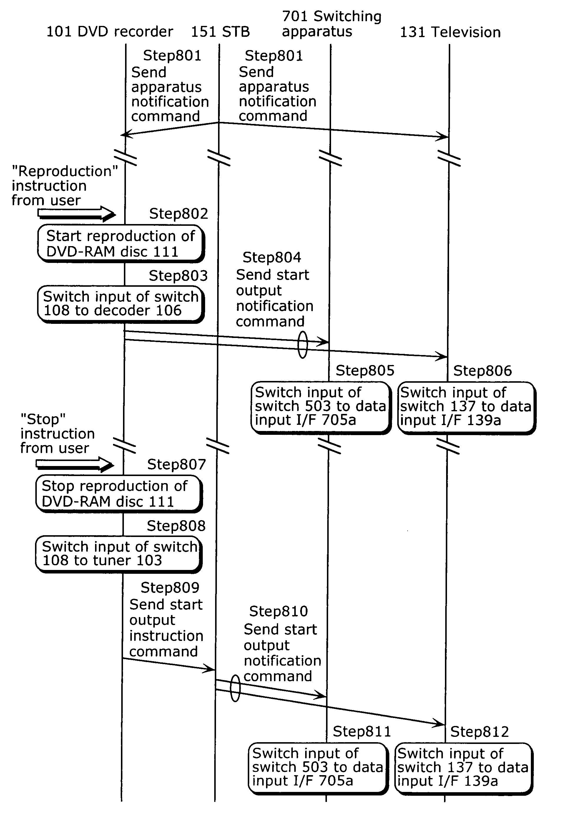
[0173]FIG. 10 is a diagram which shows an example structure of the third embodiment. The same reference numbers are assigned to the components having the same functions as those in FIG. 2. Here, a structure is adopted in which the DVD recorder 101 and the STB 151 are connected to a switching apparatus 701, rather than directly connecting the DVD recorder 101 and the STB 151 to different input terminals of the television 131, and in which the output of this switching apparatus 701 is inputted to the television 131.

[0174]The switching apparatus 701 includes a control unit 702, a switch 703, a command sending-receiving ...


PUM


Abstract

The present invention provides a reproduction apparatus capable of automatically switching an input of a television to an output from a broadcast receiver such as an STB. A television, upon receiving a notification command notifying that output of video or audio is to start, switches its input to an output from an apparatus which has sent the notification command. An STB, upon receiving an instruction command instructing that output of video or audio should be started, sends the notification command to the television. A DVD recorder includes: a decoder that reproduces video or audio recorded in a DVD-RAM disc; a data output I / F that outputs the reproduced video or audio to the television; and a command sending and receiving I / F that sends the instruction command to the STB when the output of the reproduced video or audio ends.

Description

TECHNICAL FIELD[0001]The present invention relates to a reproduction apparatus that reproduces video or audio, and particularly to technology for automatically switching the input of a television in a situation where the reproduction apparatus is connected to the television.BACKGROUND ART[0002]Nowadays, the use of televisions is not limited to the reception and viewing of television broadcasts, and they are used for a variety of purposes. For example, by connecting a digital video recorder (DVR) such as a video tape recorder (VTR) and a DVD recorder to a television, it is possible to view contents reproduced by these external apparatuses, and by connecting a home-use game machine, it is possible to enjoy playing games. For this reason, many televisions are equipped with one or more external input terminals, in addition to an antenna terminal for receiving television broadcasts. A user can switch between these input terminals by operating buttons on a remote control or the television...

Claims


Application Information

Patent Timeline
Patent Type & Authority Patents(United States)
IPC IPC(8): H04N7/14H04N5/268H04N9/80H04N5/765H04N5/935H04N5/932H04N5/44H04N5/93H04N7/173H04N21/4363
CPCG11B31/006H04N5/775H04N21/4122H04N21/4135H04N21/43615H04N7/163H04N5/765H04N5/85H04N21/488H04N21/4104H04N21/4112
Inventor YOSHIDA, JUNJIYAMADA, MASAZUMI
Owner GK BRIDGE 1
Why Eureka
Try Eureka