Portable device and portable watch

a technology of portable devices and watches, which is applied in the direction of electric winding, instruments, and horology, can solve the problems of poor workability of rotating locking members and the inability to operate locking members in a state, and achieve the effect of easy rotation and rarely hindering operation

Active Publication Date: 2012-08-07
SEIKO INSTR INC
View PDF11 Cites 24 Cited by
  • Summary
  • Abstract
  • Description
  • Claims
  • Application Information

AI Technical Summary

Benefits of technology

[0008]It is an object of the present invention is to provide a portable device and a portable watch in which an operation to restrain an operating member such as a push button so as to avoid an accidental movement of the operating member when not in use and an operation to release this restraint are achieved easily.

Problems solved by technology

Therefore, the locking member can hardly be pinched from the lateral side of the device sheath, and the workability when rotating the locking member is not good.
In particular, when it is implemented as a wristwatch, the locking member can hardly be operated in a state in which the wristwatch is worn on a wrist of a human body.

Method used


Image

  • Portable device and portable watch
  • Portable device and portable watch
  • Portable device and portable watch

Examples


first embodiment

[0043]Referring now to FIG. 1 to FIG. 8, the present invention will be described.

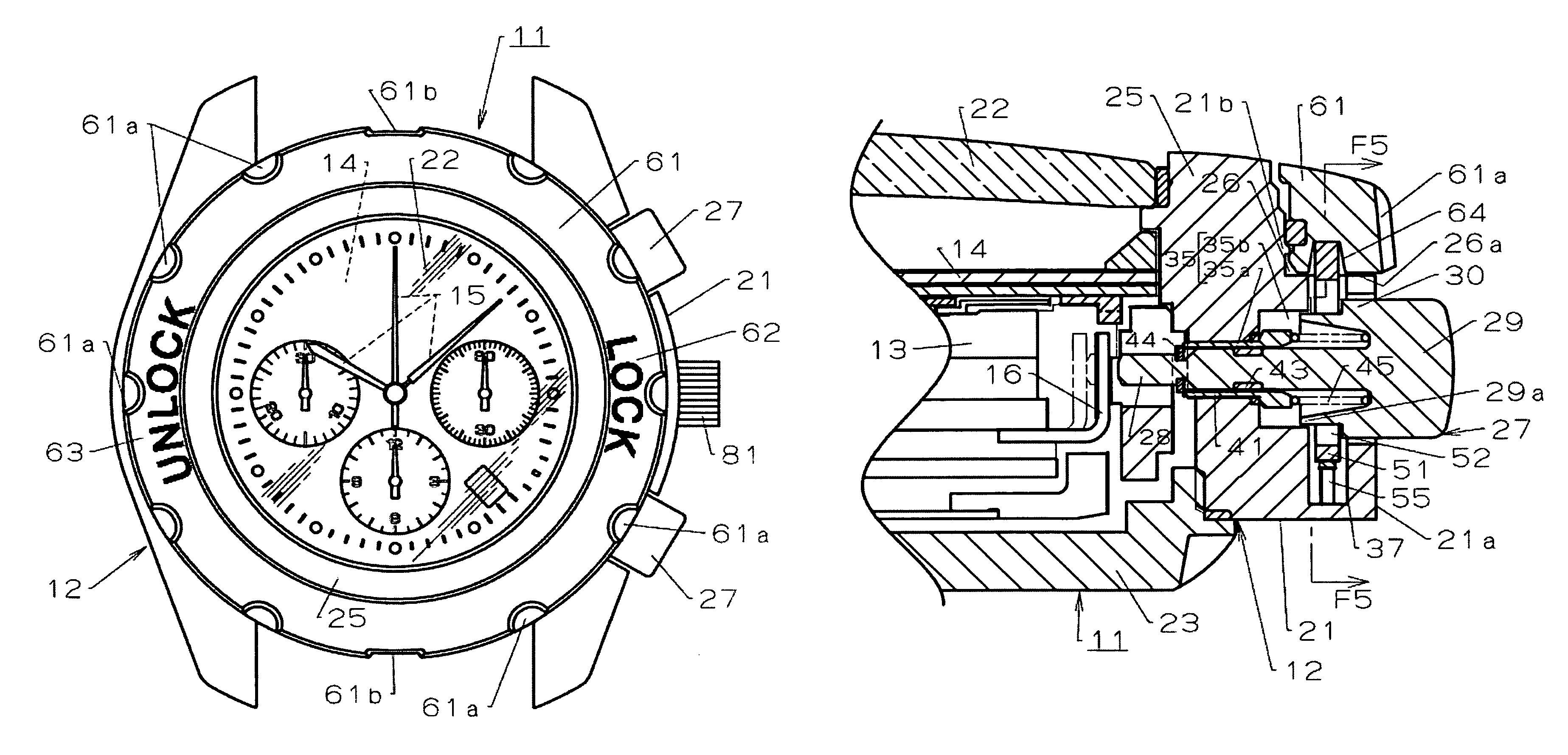
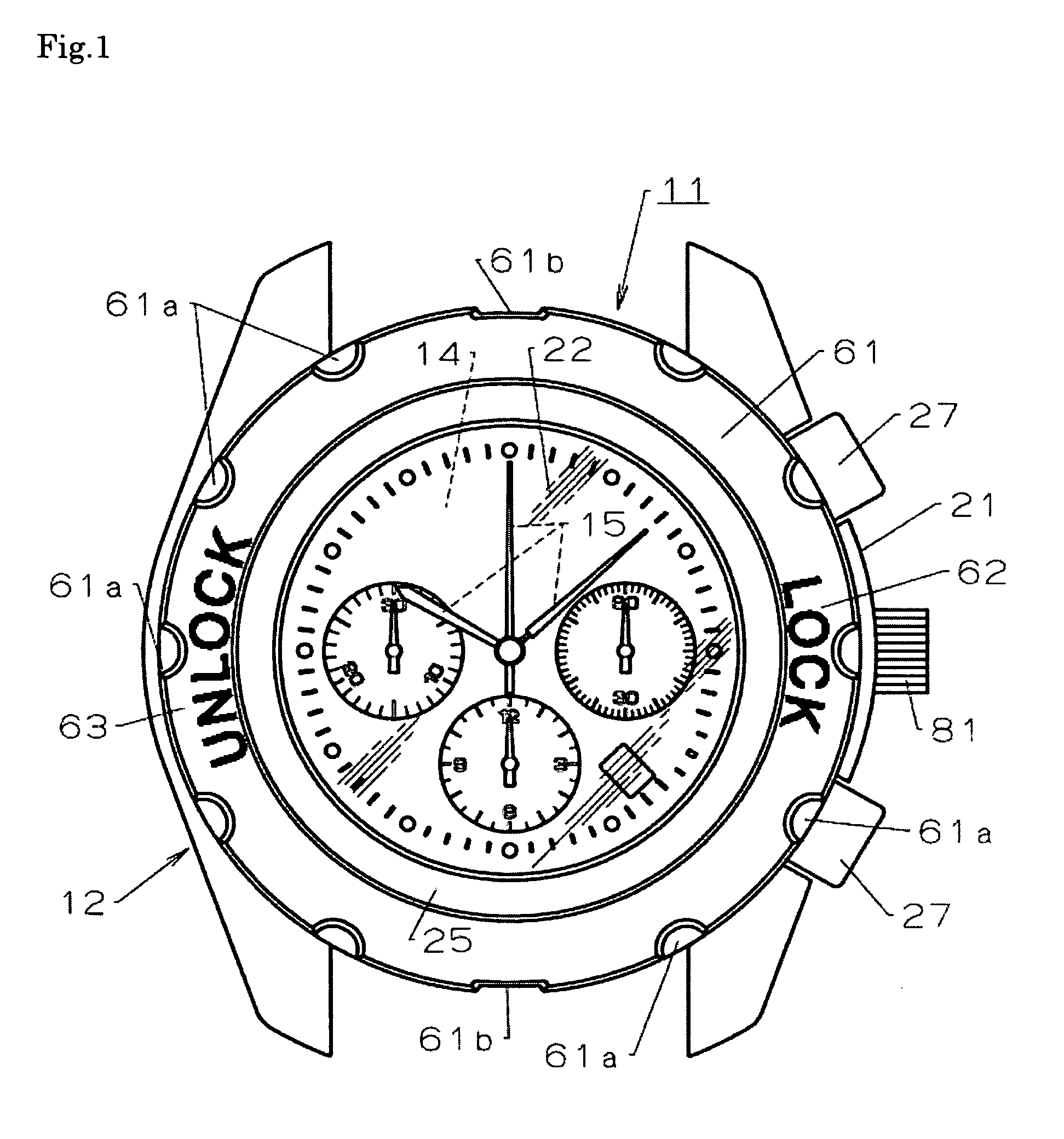
[0044]Reference numeral 11 in FIG. 1 to FIG. 3 designates a portable device, for example, a portable watch, and more specifically, a wristwatch. A watch sheath (case) 12 of the wristwatch 11, which constitutes a device sheath or case, includes a built-in component, for example, a watch movement 13 integrated therein, and a display portion, for example, a circular hour plate 14 is mounted thereon. The display of the hour plate 14 is indicated by time display hands 15 such as an hour hand, a minute hand, and a second hand driven by the watch movement 13.

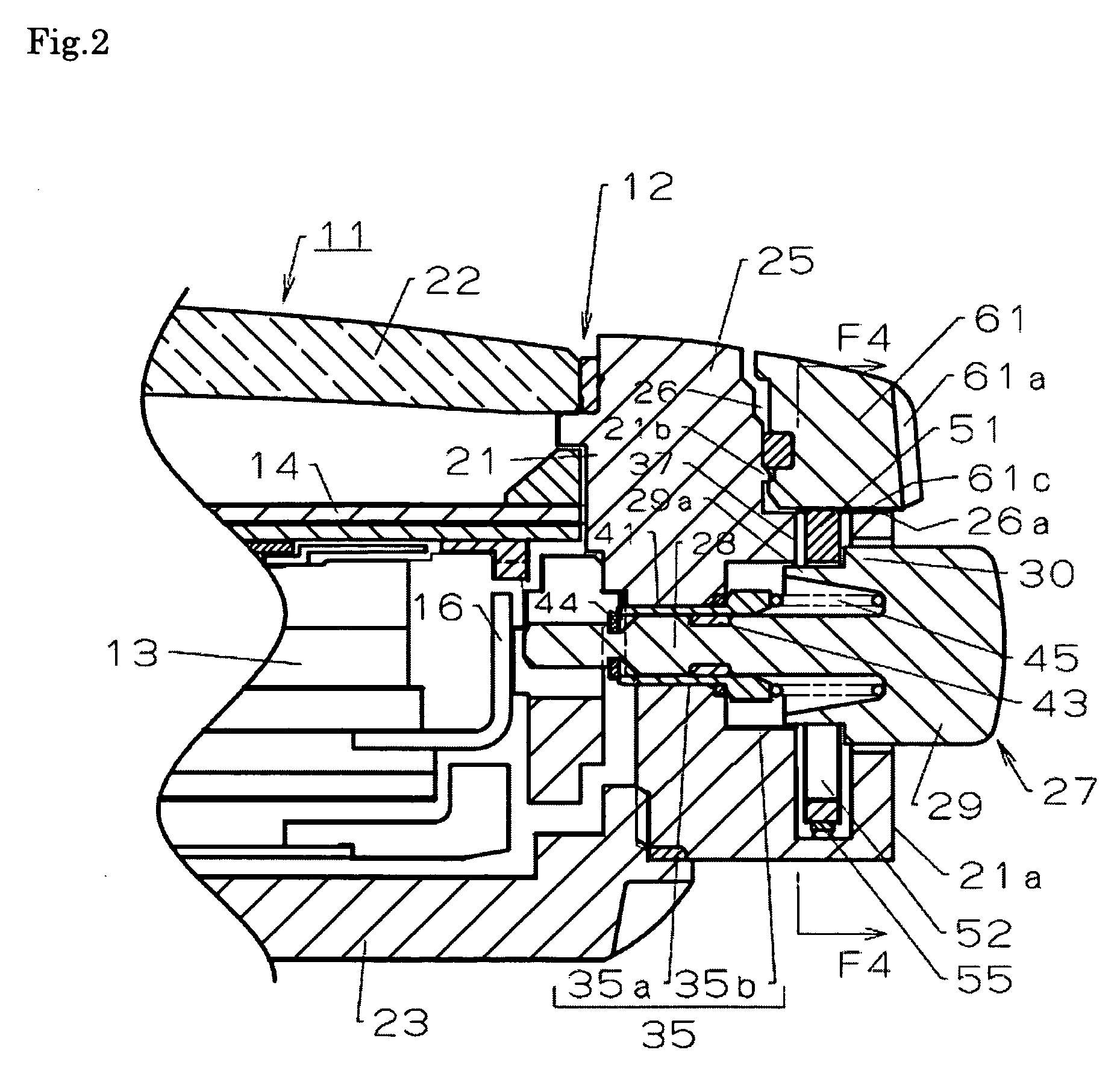
[0045]The watch movement 13 includes a contact point 16 (see FIG. 2 and FIG. 3) formed of a leaf spring or the like. When the contact point 16 is pressed by a push button, described later, the function of the watch movement 13 is changed over.

[0046]The watch sheath 12 is formed by mounting a glass 22 for allowing a viewer to see the hour plate 14 therethro...

second embodiment

[0091]In the wristwatch 11 in a state in which the winder 81 is not used such as the case of being carried, the locking member 51 is arranged at the locked position in which the unintended pulling of the winder 81 outward and sideward of the body 21 is prevented as shown in FIG. 9.

[0092]In a state in which the winder 81 is locked by the locking means, the lock surface 61c of the operating ring 61 is in contact with the edge 51a (see FIG. 4 and FIG. 5) of the locking member 51, and hence the locking member 51 is pushed downward against the urging force of the leaf spring 55 and is arranged in the locked position shown in FIG. 9. The stopper portion 51b (see FIG. 4 and FIG. 5) of the lock member 51 arranged at this locked position is fitted into the engaging portion 85 which is a recess formed on the winder 81.

[0093]Therefore, when a pulling force acts accidentally on the winder 81 in the locked state, the stopper portion 51b of the lock member 51 is caught by a wall surface of the r...


PUM


Abstract

A portable device, such as a wristwatch, has a push-button that includes an engaging portion, and the push-button is mounted on a watch sheath. A locking member and a leaf spring are arranged on the watch sheath. The locking member is movable between a locked position in which the push-button is held at a predetermined position by engagement with the engaging portion and an unlocked position where operation of the push-button is allowed. The locking member is urged by the leaf spring toward the unlocked position. A circular operating ring surrounds an hour plate mounted on the watch sheath and the operating ring is rotatably mounted to the watch sheath from the front side. The movement of the locking member between the locked position and the unlocked position is interlocked with a rotating operation of the operating ring.

Description

BACKGROUND OF THE INVENTION[0001]a) Field of the Invention[0002]The present invention relates to a portable device and a portable watch having a configuration in which an operating member such as a push button or a winder can be restrained so as not to be moved accidentally in a push-pull direction when not in use.[0003]b) Description of the Related Art[0004]Portable devices such as portable watches including wristwatches and pocket watches, stop watches, mobile phones, and portable information terminals include those having a push button for moving a contact point or the like in a device sheath mounted on the device sheath. By pushing the push button, in the case of a quartz portable watch, for example, a time display can be switched from an analogue display to a digital display, or the date or the day of the week displayed in digital can be corrected.[0005]In the related art, in the portable devices of this type, for example, in the case of a wristwatch, in order to prevent the pu...

Claims


Application Information

Patent Timeline
Patent Type & Authority Patents(United States)
IPC IPC(8): G04B29/00
CPCG04B3/043G04B3/048G04C3/001G04B37/106G04B19/283G04B19/286
Inventor HIRANUMA, HARUKIIMAI, KAZUTAKA
Owner SEIKO INSTR INC
Why Eureka
Try Eureka