Tube stub removal apparatus

a technology for removing devices and tubes, which is applied in metal-working devices, metal-working apparatuses, manufacturing tools, etc., can solve the problems of increasing the likelihood of breaking the removal device, not properly gripping a new tube, and enlarge the holes in the tube sheet to achieve the effect of convenient us

Active Publication Date: 2012-08-14
THE BABCOCK & WILCOX CO
View PDF3 Cites 0 Cited by
  • Summary
  • Abstract
  • Description
  • Claims
  • Application Information

AI Technical Summary

Benefits of technology

[0013]It is an object of the present invention to provide an apparatus and method of tube extraction that is easy to use and does not cause damage to the tube sheet upon tube withdrawal.
[0014]A further object of the invention is to provide an apparatus and method of tube extraction enabling a single technician to quickly and effectively remove tubes having belled ends from a tube sheet.
[0015]A further object of the invention is to provide an apparatus and method of tube extraction enabling a single technician to quickly and effectively remove ribbed tubes from a tube sheet.
[0016]A further object of the invention is to provide an apparatus and method of tube extraction enabling a single technician to quickly and effectively remove ribbed tubes having belled ends from a tube sheet.

Problems solved by technology

The primary problem with all these prior art structures is the imposition of expansion force on the tube precisely at the point where it is engaged with the tube sheet which can damage the metal between adjacent holes and cause the holes in the tube sheet to enlarge and not properly grip a new tube when it is expanded.
Moreover, the prior art devices require multiple devices, increasing the likelihood of breakage of the removal devices, and resulting in an increase of down-time of the structure for repairs.
While a beneficial method over prior art, the method of Ser. No. 11 / 762,104 requires multiple operators thereby increasing tube removal costs and down time related to tube removal.

Method used


Image

  • Tube stub removal apparatus
  • Tube stub removal apparatus
  • Tube stub removal apparatus

Examples


Embodiment Construction

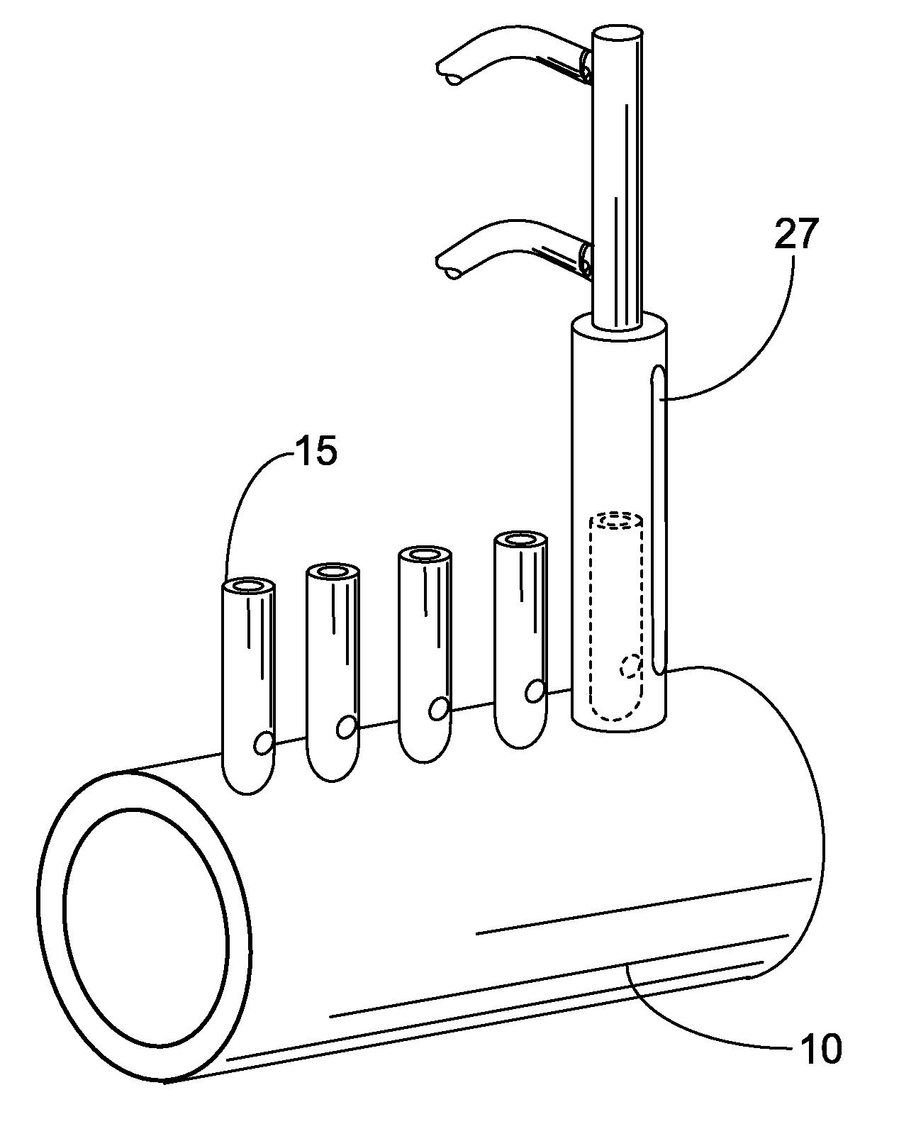
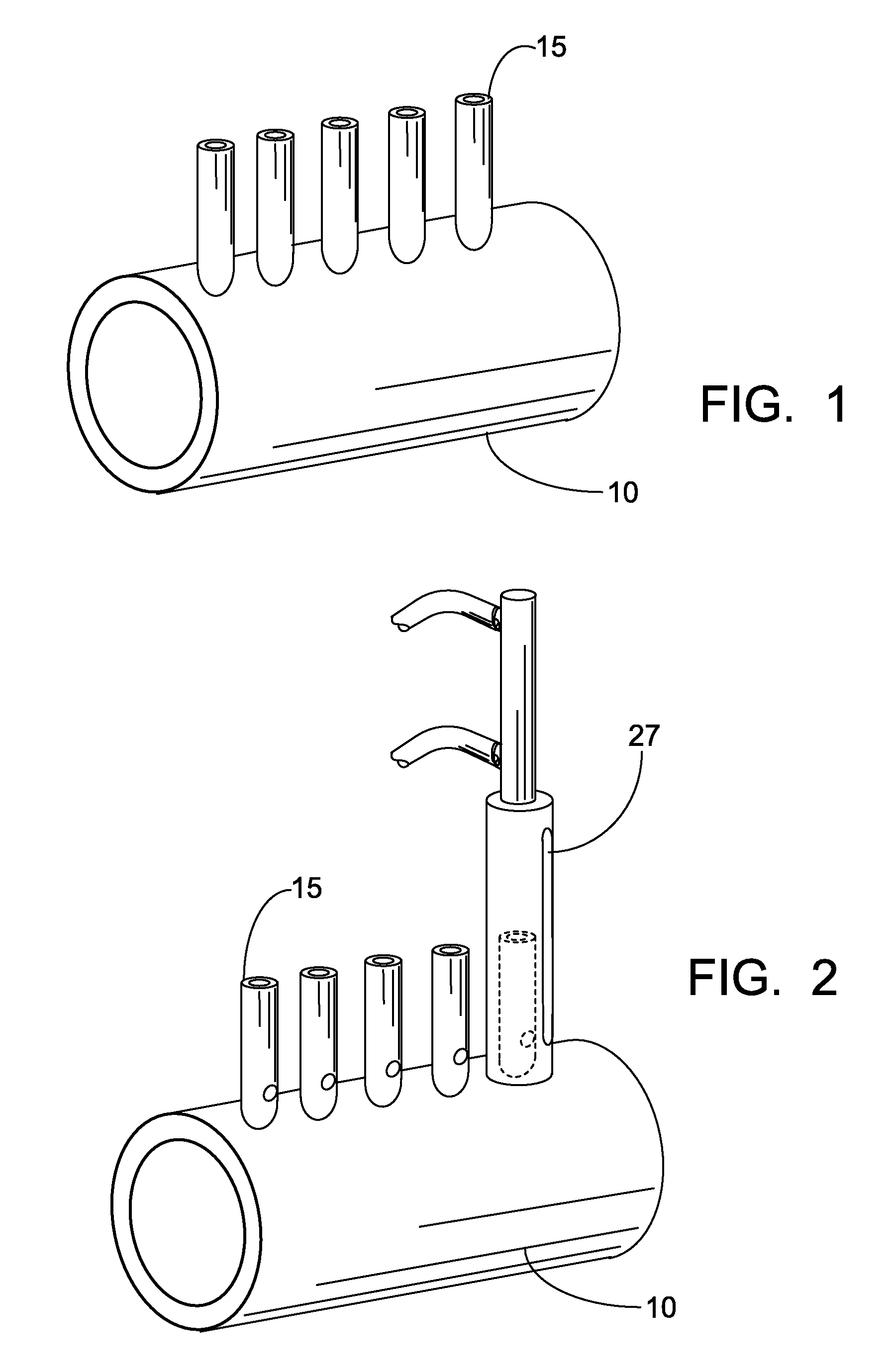
[0034]Referring now to the drawings, in which like reference numerals are used to refer to the same or similar elements, FIG. 1 is a graphical representation of a type of tube sheet known as a tube drum 10. Tube drum 10 contains at least one tube or tube stub 15, and in many cases a plurality thereof. Tubes 15 generally extended through the wall of the tube drum 10, such that a portion of the tube 15 is circumferentially surrounded by the tube drum 10. The tube end extending in the tube drum 10 may be belled 11 (FIGS. 4, 5) as a means to secure and seal the tube 15 to the tube drum 10. Ribs 14 (FIGS. 4, 5) may also be present on the tube 15 for similar purposes.

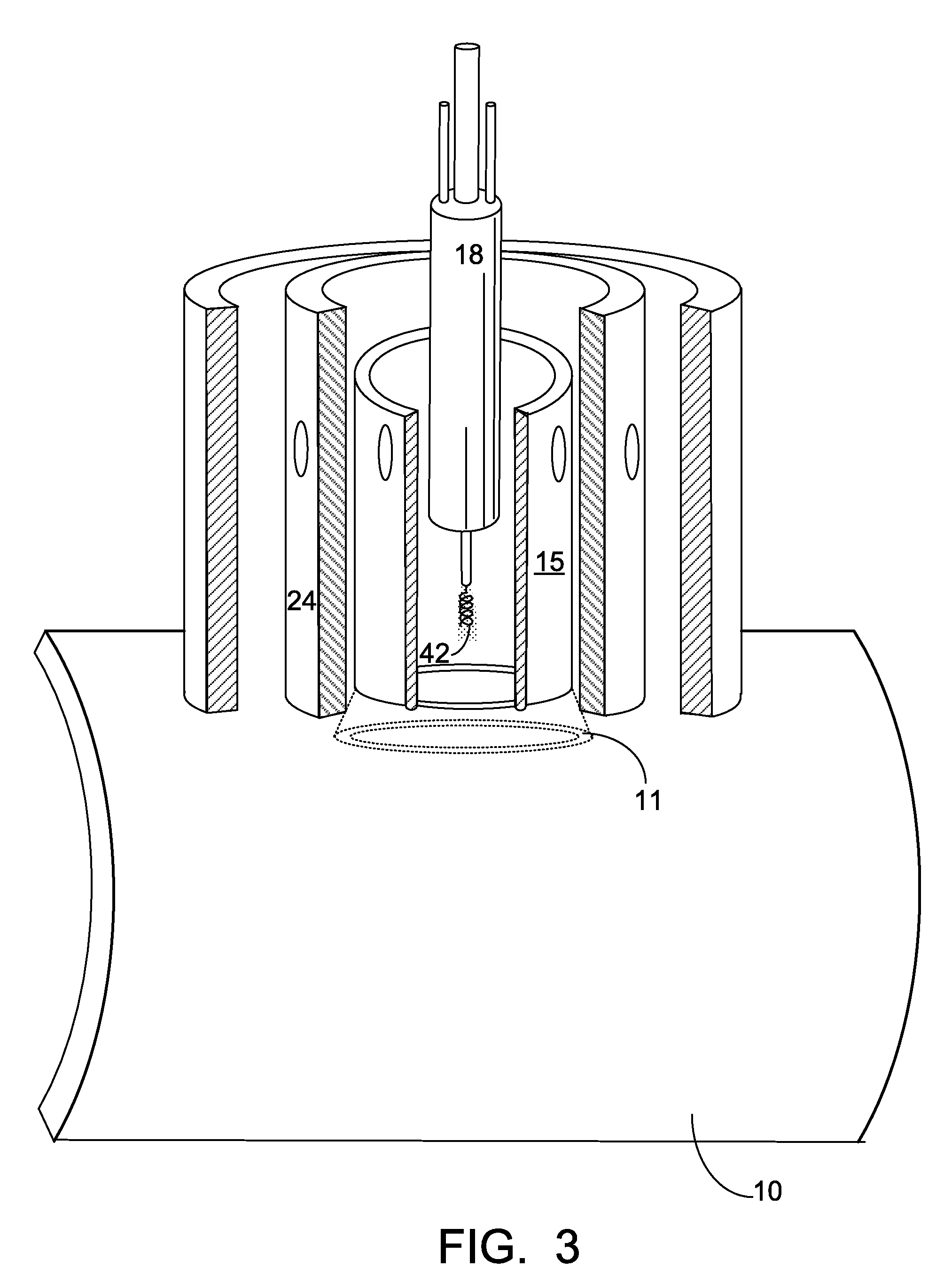
[0035]Referring now to FIG. 3. a cross sectional view of a tube removal apparatus 27 according to the present invention is show. The apparatus 27 comprises three distinct concentrically arranged elements, an inner ram 18, and outer ram 24, and a sheath 32.

[0036]In a first step, tube stub removal is accomplished by placing the...


PUM

PropertyMeasurementUnit
pressureaaaaaaaaaa
mechanically forceaaaaaaaaaa
expansion forceaaaaaaaaaa

Abstract

An improved apparatus and method of removing tubes and / or tube stubs from structures comprising multiple tubes wherein induction heating is utilized to heat the tube stub prior to removal.

Description

[0001]This application claims priority to provisional application 61 / 036,790 filed Mar. 14, 2008.FIELD AND BACKGROUND OF INVENTION[0002]The present invention relates generally to the field of tube extraction, and more particularly to an improved apparatus and method of removing tubes and / or tube stubs from structures comprising multiple tubes, such as boilers, condensers, evaporators, drums, and the like.[0003]A typical heat exchanger comprises a pair of parallel tube sheets, a plurality of baffle plates, and a plurality of heat exchanger tubes. The tube sheets are located at the ends of the heat exchanger. The baffle plates are positioned between the tube sheets and generally parallel thereto. The tubes extend between the tube sheets and through the baffle plates and are supported by the tube sheets. The tube sheets and baffle plates have a series of aligned holes formed therein, and the tubes are inserted through these holes and then expanded in the areas of the tube sheets into f...

Claims


Application Information

Patent Timeline
Patent Type & Authority Patents(United States)
IPC IPC(8): B23P6/00
CPCB23P19/025Y10T29/5383Y10T29/49352
Inventor SEYMOUR, MICHAEL J.
Owner THE BABCOCK & WILCOX CO
Why Eureka
Try Eureka