Dynamic power control, beam alignment and focus for nanoscale spectroscopy

a nano-scale spectroscopy and beam alignment technology, applied in the field of high-localized infrared (ir) spectra, can solve the problems of limited optical diffraction, high cost, and high cost of ir spectroscopy and microscopy, and achieve the effect of maximizing the respons

Active Publication Date: 2012-08-14
BRUKER NANO INC
View PDF1 Cites 19 Cited by
  • Summary
  • Abstract
  • Description
  • Claims
  • Application Information

AI Technical Summary

Problems solved by technology

Conventional IR spectroscopy and microscopy, however, have resolution on the scale of many microns, limited by optical diffraction.
It has become apparent during applications testing of a commercial nanoscale IR spectroscopy platform there is a challenge between optimizing the signal to noise ratio and the risk of sample damage.
The issue is related to the dynamic range of the measurement technique.
But if the absorbed IR energy is too high, it causes substantial heating of the sample in other areas and / or wavelengths which can lead to melting, burning and / or chemical changes in the sample.
Even at temperatures below a thermal damage threshold, the sample may soften to the point that the pressure of an AFM tip can cause local plastic deformation, altering the topography of the sample.
If the laser power is turned up large enough to resolve the smallest peaks, the sample can easily be damaged at the higher peaks.
It has also become apparent in testing by the inventors that it can be quite a challenge to determine the optimal alignment of an infrared laser beam and that this alignment process can require tedious experimentation or trial and error to find the best alignment.
First, the infrared laser beam is invisible to the eye and also to many video cameras.
While IR cameras are available they are quite expensive.
This is an imperfect solution, however, especially when the beams pass through refractive optics.
And so going from the visible guide beam to an infrared source, especially a widely tunable infrared source can create significant changes in the amount of refraction caused by a lens or other optical element.
This change in refraction can lead to differences in the position of the focus spot created by a lens, particularly when using a monochromatic visible beam as an alignment reference for a broadly tunable infrared source.
While these shifts can be minimized by aligning the incident laser beam perpendicular to optical surfaces, in practice it can be difficult to achieve such alignment over a wavelength range, especially when multiple refractive elements are used and / or when one or more of the refractive elements are replaceable by the user (e.g., a sample substrate).
Uncontrolled shifts in the focus and / or lateral position of the beam can cause loss of signal-to-noise, improper measurements of relative heights of absorption peaks, and / or discontinuities in spectra as the IR source is switched from one stage to another (for example switching from the signal to the idler in an OPO radiation source).
This can also be a significant issue since the IR beam may be focused to a diffraction limited spot on the scale of a few to a few 10's of microns.
It is possible to defocus the laser beam to create a larger spot, but-this can compromise the signal-to-noise ratio, especially for weak absorptions and / or wavelengths where the laser source has limited power.
This has led to the problem of some spectroscopic measurements being constrained in some cases to a single laser stage where the beam pointing errors are sufficiently small to be tolerable.
Each of the laser heads may also have a slightly different emission angle making it very difficult to maintain the focus spot at the point of tip-surface interaction over a broad wavelength range.

Method used


Image

  • Dynamic power control, beam alignment and focus for nanoscale spectroscopy
  • Dynamic power control, beam alignment and focus for nanoscale spectroscopy
  • Dynamic power control, beam alignment and focus for nanoscale spectroscopy

Examples


Embodiment Construction

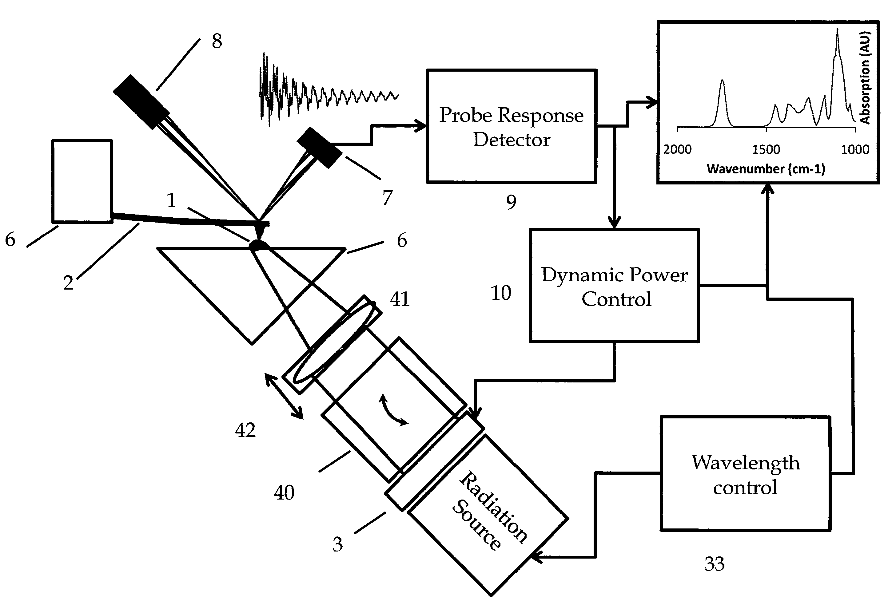
[0023]Referring to FIG. 4 the elements required to practice the invention are shown. Sample 1 is probed by an AFM with a cantilever probe 2. The interaction between the probe and sample may be contact, non-contact, near contact, intermittent contact and / or tapping or other method of interaction that generates a measurable probe response as a function of the interaction. In one embodiment an optical lever arm probe motion sensor comprising a source 8 and photodetector 7 interfaced to Probe Response Detector 9 measures a response of the AFM cantilever 2. The measured probe response may be deflection, motion, oscillation, phase or other properties of the mechanical response of the probe. Many techniques can be employed to measure the cantilever motion. For example AFMs have been built where the cantilever deflection is performed by electron tunneling, capacitive detection, interferometry, magnetic, piezoelectric, piezoresistive and thermal sensing, for example. Any mechanism that detec...


PUM


Abstract

Dynamic IR radiation power control, beam steering and focus adjustment for use in a nanoscale IR spectroscopy system based on an Atomic Force Microscope. During illumination with a beam from an IR source, an AFM probe tip interaction with a sample due to local IR sample absorption is monitored. The power of the illumination at the sample is dynamically decreased to minimize sample overheating in locations / wavelengths where absorption is high and increased in locations / wavelengths where absorption is low to maintain signal to noise. Beam alignment and focus optimization as a function of wavelength are automatically performed.

Description

RELATED APPLICATIONS[0001]This application is a Continuation-in-Part of U.S. application Ser. No. 12 / 660,266 filed Feb. 23, 2010FEDERALLY SPONSORED RESEARCH[0002]This work was supported in part by NIST-ATP 70NANB7H7025 and NSF-SBIR 0750512 The government retains certain rights.SEQUENCE LISTING[0003]Not ApplicableBACKGROUND OF THE INVENTION[0004]This invention is related to highly localized Infrared (IR) spectra on a sample surface utilizing an Atomic Force Microscope (AFM) and a variable wavelength pulsed IR source, and specifically to dynamic IR power control for maximizing dynamic range while minimizing sample damage.[0005]IR spectroscopy is a useful tool in many analytical fields such as polymer science and biology. Conventional IR spectroscopy and microscopy, however, have resolution on the scale of many microns, limited by optical diffraction. It would be particularly useful to perform IR spectroscopy on a highly localized scale, on the order of biological organelles or smaller...

Claims


Application Information

Patent Timeline
Patent Type & Authority Patents(United States)
IPC IPC(8): G01J5/00
CPCB82Y35/00G01Q30/02G01N21/3563
Inventor PRATER, CRAIGLO, MICHAELGOTTHARD, DOUGKURTZ, ANTHONYKJOLLER, KEVIN
Owner BRUKER NANO INC
Why Eureka
Try Eureka