
Electronic apparatus

a technology of electronic equipment and switch, which is applied in the field of magnetic power saving switch, can solve the problems of power affecting the strength of magnetic detectors, and inordinate energy consumption of display components of portable electronic devices when they are operated

Inactive Publication Date: 2012-08-14
HONG FU JIN PRECISION IND (SHENZHEN) CO LTD +1
View PDF11 Cites 42 Cited by
  • Summary
  • Abstract
  • Description
  • Claims
  • Application Information

AI Technical Summary

Benefits of technology

The present invention is about an electronic device with a main body, lid, magnetic detecting unit, and magnetic shield member. The lid can be opened and closed and the detecting unit can detect the position of the lid using a magnetic field. The magnetic shield member is placed next to the magnetic body to prevent the magnetic field from affecting the second side of the magnetic body. The technical effect of this invention is to provide a reliable and accurate way to detect the position of an electronic device's lid using a magnetic field.

Problems solved by technology

In general, the display component of these portable electronic devices consumes an inordinate amount of energy when the portable electronic devices are operated.
Magnetic substances, such as metal keys, near or adjacent to the portable electronic device may affect the strength of the magnetic detector.
As such the display may not turn off even when the lid is very close to the magnetic detector and the display will consume power even when the lid is closed.
Thus, these magnetic substances next to the portable electronic device manually, may cause great inconvenience to the user.

Method used


Image

  • Electronic apparatus
  • Electronic apparatus
  • Electronic apparatus

Examples


Embodiment Construction

[0016]Reference will now be made to the drawing figures to describe the various present embodiments in detail.

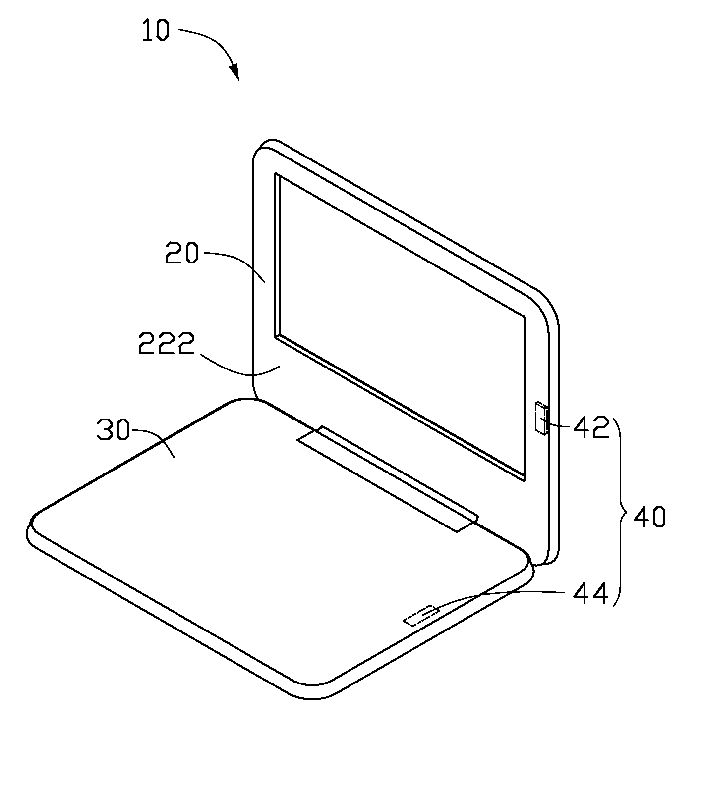
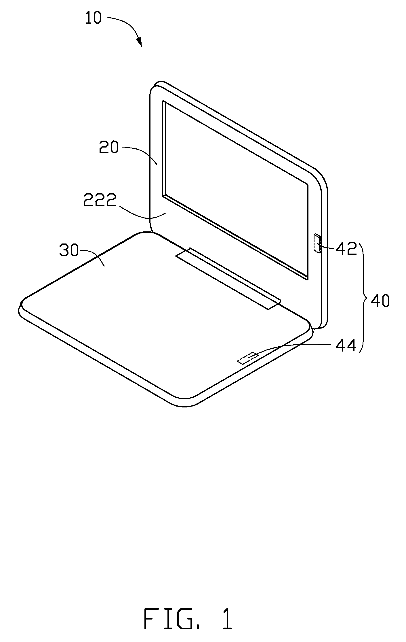
[0017]Referring to FIG. 1, an electronic apparatus 10 includes a main body 30, a lid 20 and a magnetic detecting unit 40. The lid 20 is pivotably connected to a rear side of the main body 30. The lid 20 is pivotable with respect to the main body 30, so that the lid 20 can be rotated between an open position and a closed position according to user's requirements.

[0018]The magnetic detecting unit 40 includes a magnetic body 42 and a magnetic detector 44. The magnetic body 42 is mounted on the lid 20. The magnetic detector 44 is mounted on the main body 30. The magnetic detector 44 faces the magnetic body 42 of the lid 20 when the lid 20 is in the closed position. Alternatively, the locations of the magnetic body 42 and the magnetic detector 44 can be interchangeable.

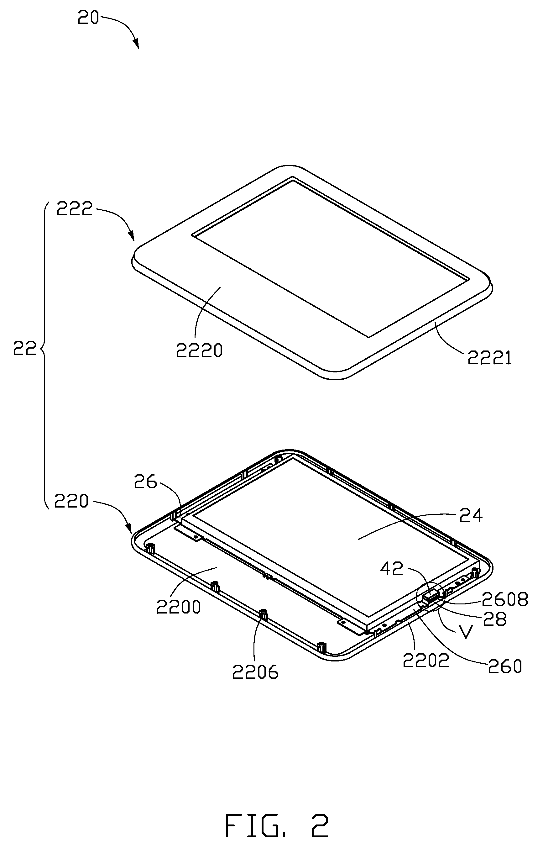
[0019]Referring to FIG. 2, the lid 20 includes a shell 22, a screen 24, a fixing frame 26 and a magnetic shield ...


PUM


Abstract

An electronic apparatus (10) includes a main body (30), a lid (20) pivotably connected with a side of the main body, a magnetic detecting unit (40) and a magnetic shield member (28). The detecting unit includes a magnetic body (42) mounted on one of the main body or the lid and a magnetic detector (44) mounted on the other one of the main body or the lid, respectively. The magnetic body has a facing side (421) to face the magnetic detector. The magnetic detector detects a position of the lid according to a magnetic field intensity of the magnetic body. The magnetic shield member is disposed at a distance from the facing side and adjacent to a second side (422) of the magnetic body, to prevent the magnetic field from extending in the direction of the second side of the magnetic body.

Description

BACKGROUND[0001]1. Technical Field[0002]The present invention generally relates to power saving switches, and more particularly to a magnetic power saving switch for a portable electronic apparatus.[0003]2. Description of Related Art[0004]In recent years, portable electronic devices such as mobile phones, personal data assistants (PDA), hand-held computers, and notebook computers have been widely used due to their convenience and practicality. In general, the display component of these portable electronic devices consumes an inordinate amount of energy when the portable electronic devices are operated. The best way to save energy is by powering off the screen while keeping the portable electronic device operated when not in use. This will help extend the life of the screen and decrease electromagnetic radiation from the screen.[0005]One technique of turning off the display when the lid is closed is by a controlling switch. Portable electronic devices include a main body and a lid pi...

Claims


Application Information

Patent Timeline
Patent Type & Authority Patents(United States)
IPC IPC(8): H05K5/00H05K7/00
CPCG06F1/1616G06F1/1677G06F1/3203Y10T292/1029
Inventor WANG, HE-LILI, HONGZHANG, TINGZHAO, TING-TING
Owner HONG FU JIN PRECISION IND (SHENZHEN) CO LTD
Learn More