Assist grip

a technology of assist grip and hinge portion, which is applied in the direction of cell components, manufacturing tools, cell component details, etc., can solve the problems of difficult to manage the rotational torque of the hinge portion at a previously set constant value, troublesome and difficult work, and easy noise, etc., to facilitate the design of assist grip, facilitate the effect of parts management and easy coloring

Active Publication Date: 2012-08-21
HOWA PLASTICS CO LTD +1
View PDF15 Cites 15 Cited by
  • Summary
  • Abstract
  • Description
  • Claims
  • Application Information

AI Technical Summary

Benefits of technology

[0011]It is an object of the present invention to provide an assist grip that allows easily mounting a torsion coil spring for urging a grip body in a rotating direction on a hinge portion, and capable of stably imparting an appropriate spring force of the torsion coil spring to the grip body.

Problems solved by technology

The torsion coil spring, at the time of assembly, while urging the grip body up to the unused position against the hinge portion, is to be attached between a pair of support pieces on the lower portion of the hinge portion, however, the torsion coil spring needs to be oriented in a predetermined direction as its direction and mounted being urged in a torsional state, and thus a work for mounting a small-sized torsion coil spring into such a configuration by hand is troublesome and difficult work.
Therefore, when the torsion coil spring is attached in an inclined manner between the pair of support pieces of the hinge portion, it is difficult to impart a constant torsional torque to the hinge portion in a torsional direction thereof, and rotational torque between the hinge portion and the grip body by the torsion coil spring fluctuates for every product, so that it becomes difficult to manage the rotational torque of the hinge portion at a previously set constant value.
In addition, there has been a problem such that, when the torsion coil spring is attached with its axis obliquely shifted with respect to the hinge shaft of the hinge portion on which the torsion coil spring is mounted, noise is likely to occur due to friction between coil wires or due to friction between the torsion coil spring and a wall surface of the hinge recess portion of the grip body when the grip body is operated to rotate with respect to the hinge portion.

Method used


Image

  • Assist grip
  • Assist grip
  • Assist grip

Examples


Embodiment Construction

[0040]Hereinafter, the present invention will be described based on embodiments shown in the drawings. However, the present invention is by no means limited to the embodiments. All modifications within the requirements of the claims or equivalents thereof with respect to the requirements should be included in the scope of the claims.

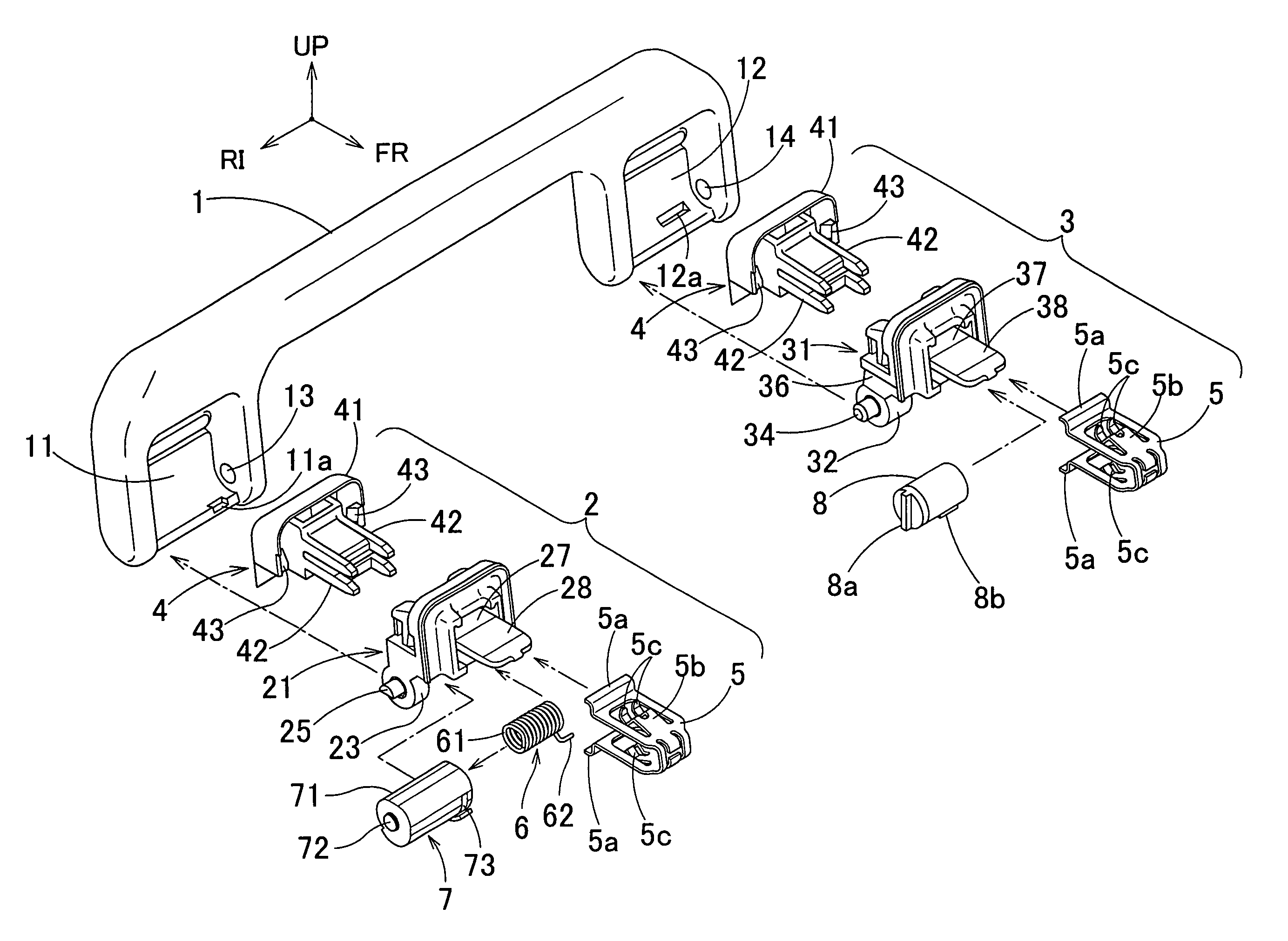
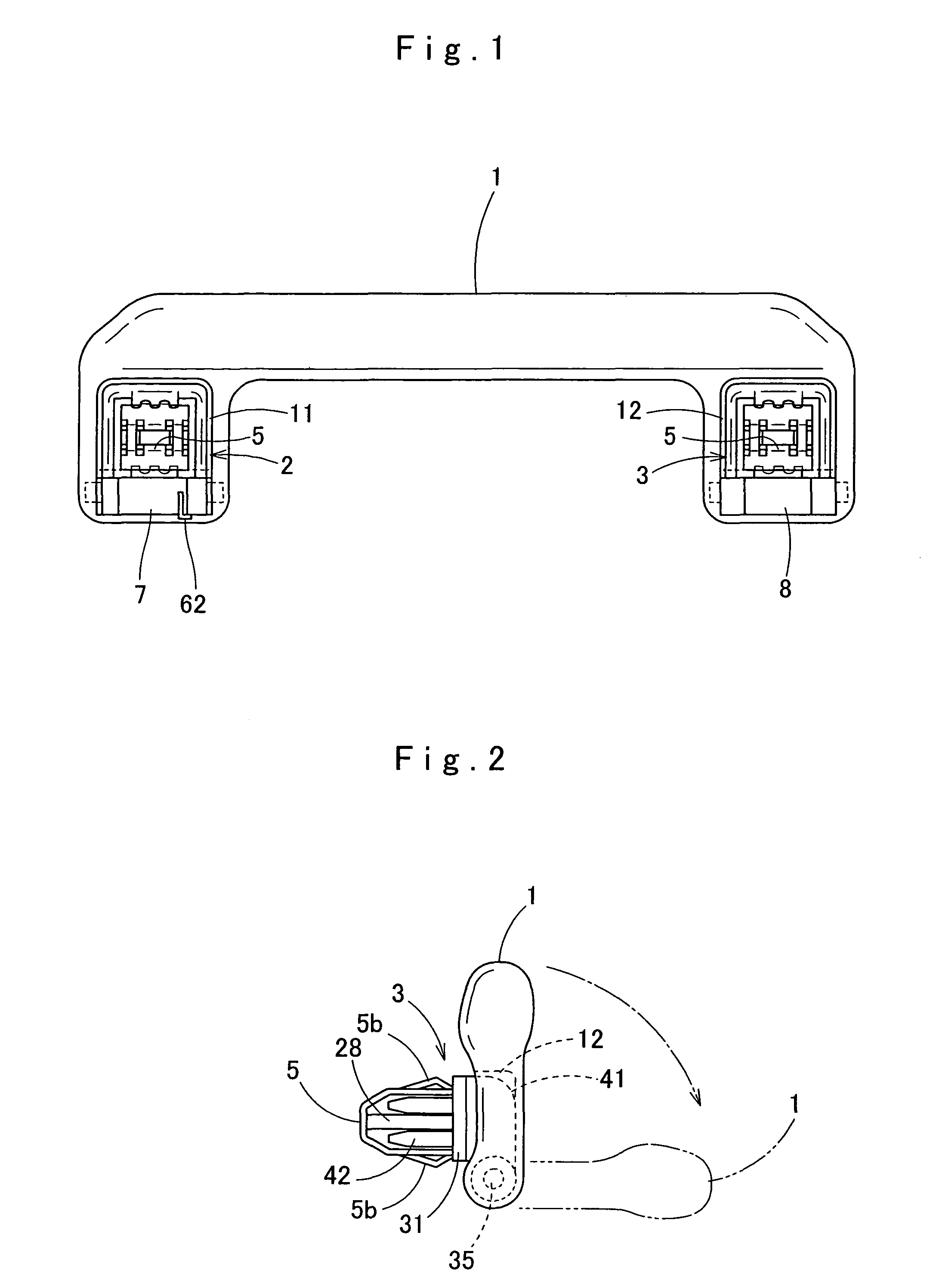
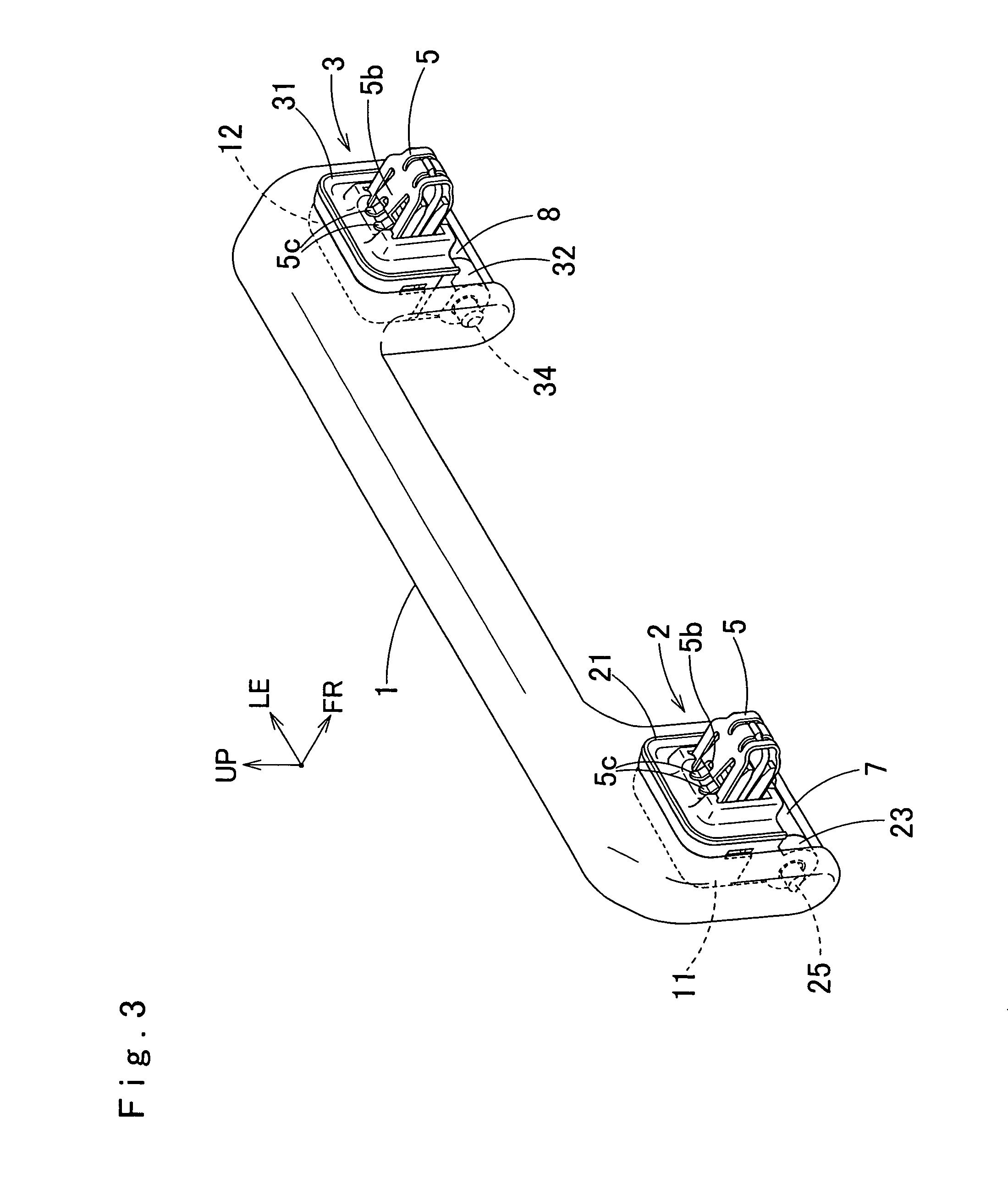
[0041]FIG. 1 shows a back view of an assist grip for an automobile, FIG. 2 shows a left side view thereof, FIG. 3 shows a perspective view from the back thereof, and FIG. 4 shows an exploded perspective view thereof. In addition, the left, right, up, and down to be used in the following description indicate the left, right, up, and down when an assist grip in a mounted posture is viewed from the front, respectively, and an arrow FR shown by illustration indicates the front direction of an assist grip, and an arrow LE, the left direction, and an arrow RI, the right direction, and an arrow UP, the up direction, and an arrow RE, the rear direction.

[0042]As ...


PUM


Abstract

An assist grip of the present invention includes a grip body provided at both side base portions thereof with hinge recess portions and a hinge portion rotatably and pivotally supported in each of the hinge recess portions of both sides, and is fixed via the hinge portion to a to-be-fixed portion in an automobile. In a pivot support portion of the hinge portion, an outer support piece and an inner support piece are provided at a distance from each other, and between the inner support piece and the outer support piece, a torsion coil spring stored in a spring case is inserted. One end portion of the torsion coil spring is locked to an inside of the spring case, and the other end portion of the torsion coil spring projects from the spring case and is locked to a part of the grip body.

Description

BACKGROUND OF THE INVENTION[0001]1. Field of the Invention[0002]The present invention relates to an assist grip to be attached to a sealing surface or the like in an automobile cabin, and more particularly, to an assist grip a grip body of which is rotatably fixed to a to-be-fixed portion in an automobile via a hinge portion.[0003]2. Description of Related Art[0004]To a sealing surface in an automobile cabin, an assist grip is attached to allow a passenger to support his / her body in the cabin. As assist grips of this type, ones having such a structure that recess portions are formed at both sides of a grip body, a hinge portion is rotatably attached in the recess portion, and the grip body is rotatably mounted via the hinge portion have been mounted on various automobiles.[0005]On the hinge portion of an assist grip of this type, as described in, for example, Japanese Published Patent Application No. 2005-138823 A, a torsion coil spring for urging around a hinge shaft thereof is mou...

Claims


Application Information

Patent Timeline
Patent Type & Authority Patents(United States)
IPC IPC(8): A45C13/22
CPCB60N3/023B60N3/026Y10T16/44Y10T16/513
Inventor KAJIO, HIDEKIKAWAKAMI, SHOUJIKAWAMURA, KAZUHIROSAKUMA, YOSHIYUKI
Owner HOWA PLASTICS CO LTD
Why Eureka
Try Eureka