Damper in a washing machine and fabricating method of the same

a technology of damper and washing machine, which is applied in the direction of shock absorbers, mechanical devices, other washing machines, etc., can solve the problems of inconvenience of use, damper b>8/b> may be damaged, and the vibration cannot be rapidly attenuated, so as to prevent the damper from being damaged and reduce the vibration in the washing machine

Inactive Publication Date: 2007-10-16
LG ELECTRONICS INC
View PDF18 Cites 3 Cited by
  • Summary
  • Abstract
  • Description
  • Claims
  • Application Information

AI Technical Summary

Benefits of technology

[0022]One object of the present invention is to provide a damper for a washing machine, in which an appropriate damping force is applied in case a large or small amount of vibration is generated, thereby rapidly reducing an amount of vibration.
[0023]Another object of the present invention is to provide a damper for a washing machine, in which an appropriate damping force is applied to rapidly reduce an amount of vibration, and an amount of noise occurring due to a collision of parts during a generation of vibration.
[0024]Further another object of the present invention is to provide a damper for a washing machine, which is capable of preventing a damage of the damper.
[0034]The damper for the washing machine and the method for forming the same can rapidly reduce an amount of vibration occurring in the washing machine.
[0035]Further, it is possible to prevent the damper from being damaged due to a large amount of vibration.

Problems solved by technology

Meanwhile, the case of large amount of vibration and the case of small amount of vibration may occur in the drum washing machine.
Therefore, in case a small amount of vibration occurs, the damper 8 acts as a rigid body, such that an amount of vibration cannot be rapidly attenuated due to a vibration exceeding a displacement limit of the damper 8 and the damper 8 may be damaged.
Since such a conventional damper cannot properly cope with the change in an amount of vibration, noise and vibration occur seriously, thereby causing an inconvenience of use.

Method used


Image

  • Damper in a washing machine and fabricating method of the same
  • Damper in a washing machine and fabricating method of the same
  • Damper in a washing machine and fabricating method of the same

Examples


first embodiment

[0076]FIGS. 3 to 6 illustrate the present invention.

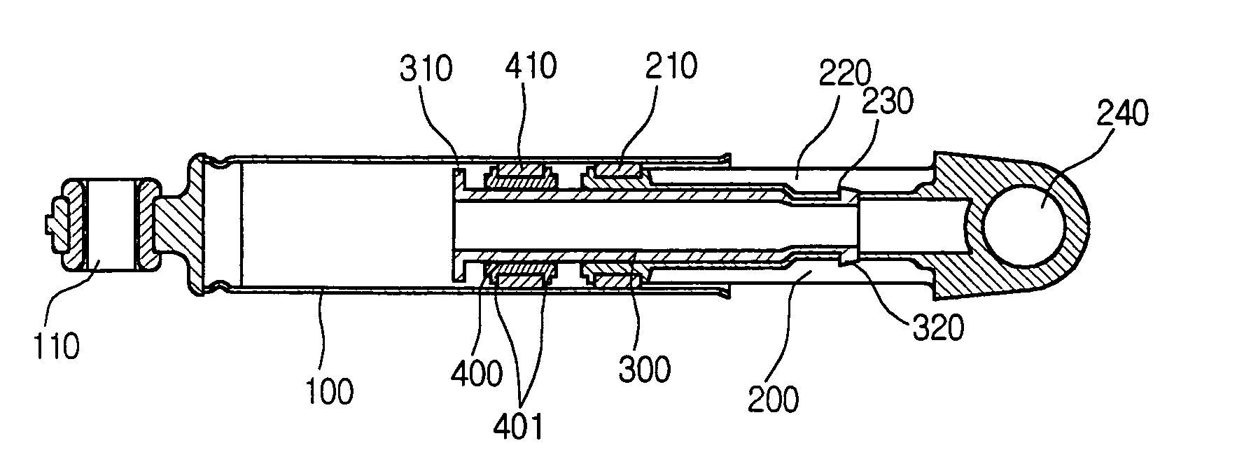
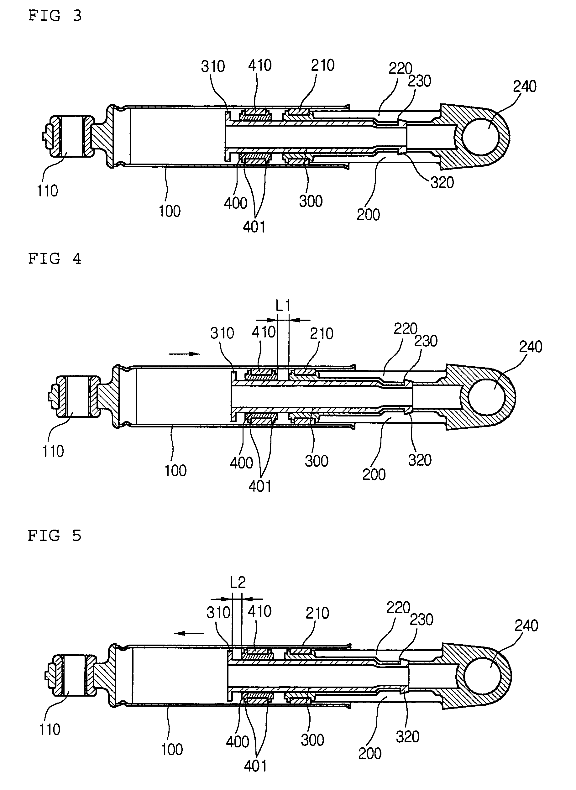
[0077]FIG. 3 is a sectional view of a damper for a washing machine according to a first embodiment of the present invention.

[0078]Referring to FIG. 3, the damper for the washing machine includes a hollow cylinder 100, a piston body 200 inserted into the hollow portion of the cylinder 100, an extension bar 300 coupled to the piston body 200 and extended therefrom, and a circular friction ring 400 that surficially contacts with an inner circumferential surface of the cylinder 100 in a state that a free movement is possible because a predetermined interval is maintained with an outer circumferential surface of the extension bar 300.

[0079]Additionally, the damper for the washing machine includes a tub fixing opening 110 formed at one end portion of the cylinder 100 and connected to a tub of the washing machine, a case fixing opening 240 formed at one end portion of the piston body 200 and connected to a case of the washing machine, a f...

second embodiment

[0101]FIG. 7 is a sectional view of a damper for a washing machine according to the present invention

[0102]Referring to FIG. 7, a structure of the damper for the washing machine according to the second embodiment of the present invention is mostly similar to that of the damper according to the first embodiment of the present invention. A difference is that a third friction member 420 except for the second friction member 410 is additionally formed on the outer circumferential surface of the friction ring 410. By doing so, the damping force applied to the damper is generally increased much more.

[0103]In other words, the damping force (F1) is identical to the first embodiment till before the displacement of the cylinder 100 reaches a predetermined distance. On the other hand, if the displacement of the cylinder 100 exceeds the predetermined distance, a damping force is larger than the damping force (F1+F2) of the first embodiment. As a result, the vibration can be attenuated more rapi...

third embodiment

[0105]FIGS. 8 to 10 illustrate the present invention.

[0106]Referring to FIG. 8, a structure of the damper for the washing machine according to the third embodiment of the present invention is mostly similar to that of the damper according to the first embodiment of the present invention. A difference is that the damper according to the third embodiment of the present invention further includes a first elastic member 320 formed on an end portion of the piston body 200, and a second elastic member 340 formed on an inner surface of the circumferential stopper 310.

[0107]In more detail, the second elastic member 340 of a soft elastic material, such as a rubber, is inserted into the inner surface of the circumferential stopper 310 in order to allow the circumferential stopper 310 and the friction ring 400 to softly contact with each other without any impact. Herein, an effect of the second elastic member 340 will be described below. Since a large vibration occurs with a short frequency at...


PUM


Abstract

A damper for a washing machine includes: a cylinder; a piston body having one end inserted into the cylinder; a first friction member interposed in a contact surface between the piston body and the cylinder; an extension bar extended from an inserted portion of the piston body, the extension bar having a circumferential stopper at the extended portion; a friction ring formed between the circumferential stopper and the first friction member; and a second friction member formed on an outer circumferential surface of the friction ring to contact with an inner surface of the cylinder.

Description

TECHNICAL FIELD[0001]The present invention relates to a damper structure, and more particularly to a multi-step damper structure of a washing machine and a method for forming the same, in which a damping force is applied with multi-steps according to an amount of vibration occurring in the washing machine, and a large or small amount of vibration is attenuated appropriately to thereby operate the washing machine in a low noise state.BACKGROUND ART[0002]Washing machines are classified into a drum type, an agitator type and a pulsator type according to a washing method. Specifically, the drum washing machine has a protrusion portion formed on an inner wall of the cylinder. A washing operation is performed by an impact force occurring when a laundry is lifted up and dropped down along an inner circumferential surface of the drum due to the protrusion portion during a rotation of the drum.[0003]Recently, the drum washing machine is widely used since a laundry is less damaged and a small...

Claims


Application Information

Patent Timeline
Patent Type & Authority Patents(United States)
IPC IPC(8): F16F9/12D06F37/20D06F37/22F16F9/34
CPCD06F37/20F16F7/09
Inventor PARK, SEOK KYUPARK, GWAN RYONG
Owner LG ELECTRONICS INC
Why Eureka
Try Eureka