Downhole vibration dampener

a vibration dampener and downhole technology, applied in the direction of drilling pipes, directional drilling, borehole/well accessories, etc., can solve the problems of substantial vibration caused by the drill bit, unsatisfactory, and the drill bit to begin to bounce off the bottom of the hole, so as to achieve the effect of dampening vibration

Active Publication Date: 2012-06-26
RIVAL DOWNHOLE TOOLS LC
View PDF12 Cites 10 Cited by
  • Summary
  • Abstract
  • Description
  • Claims
  • Application Information

AI Technical Summary

Benefits of technology

[0010]The primary aspect of the present invention is to dampen vibrations caused by the act of drilling a well bore.
[0012]In accordance with the principles of the present invention, a down hole vibration dampener is disclosed that uses a set of polyurethane rings and specially designed steel support rings to create a shock absorber within the drill string to reduce the amount of vibration in the drill string and dampen the vibrations caused by drilling a well bore. The down hole vibration dampener of the invention includes a hollow cylindrical housing having an interior and an exterior and having a lower connecting extent for connection to one part of a drill string. A splined mandrel extends longitudinally into the interior of the cylindrical housing and has an upper connecting extent for connection to another part of a drill string. The splined mandrel also has a through bore for the passage of fluids. A seal structure is present in longitudinally spaced relation between the interior of the cylindrical housing and the splined mandrel and forms a liquid receiving chamber. A vibration dampening structure is located in the liquid receiving chamber, the vibration dampening structure being compressible longitudinally to absorb vibration and shock loads. The preferred vibration dampening structure is made up of a series of resilient rings formed of a polymeric material which are separated by a series of interspersed metal rings which give the resilient rings support and definition while being subjected to a load.
[0013]In a preferred embodiment of the invention, the resilient rings are formed of polyurethane and the metal rings are formed of steel. The polyurethane rings are shaped and engineered in such a manner that when the set of polyurethane rings are subjected to a shock load, the metal rings will not touch one another except under maximum load circumstances. As a result, the polyurethane rings and interspersed steel rings form a vibration dampening column, the column being encased on either of opposite ends thereof by metallic end rings. Preferably, the polyurethane rings each have an upper circumferential surface and a lower circumferential surface at least a selected one of which is provided with machined ridges which act as further shock absorbers and to improve the deformation properties of the polyurethane rings. The ridges which are present on the selected circumferential surface of the polyurethane rings are on the order of about 0.050 inch in height. The interspersed steel rings have chamfered outer edges in order that the edges not gouge the inner surface of the cylindrical outer housing nor gouge the outer surface of the spline mandrel.

Problems solved by technology

When a well is being drilled, the vibration caused by the drill bit is substantial.
In some cases, the vibration frequency caused by the drilling can reach the harmonic frequency of the drill string, which causes the drill bit to begin bouncing off of the bottom of the hole.
This condition is completely undesirable, and is harmful to the drill bit and the other tools of the drill string.
Slip-stick can also reduce penetration rates, which adds to the over all cost of drilling a borehole.
The several forms of vibration dampeners and shock absorbers known in the prior art all suffer from one or more deficiencies.
Other limitations of the related art will become apparent to those of skill in the art upon a reading of the specification and a study of the drawings.

Method used


Image

  • Downhole vibration dampener
  • Downhole vibration dampener
  • Downhole vibration dampener

Examples


Embodiment Construction

[0023]Before explaining the disclosed embodiment of the present invention in detail, it is to be understood that the invention is not limited in its application to the details of the particular arrangement shown, since the invention is capable of other embodiments. Exemplary embodiments are illustrated in referenced figures of the drawings. It is intended that the embodiments and figures disclosed herein are to be considered illustrative rather than limiting. Also, the terminology used herein is for the purpose of description and not of limitation.

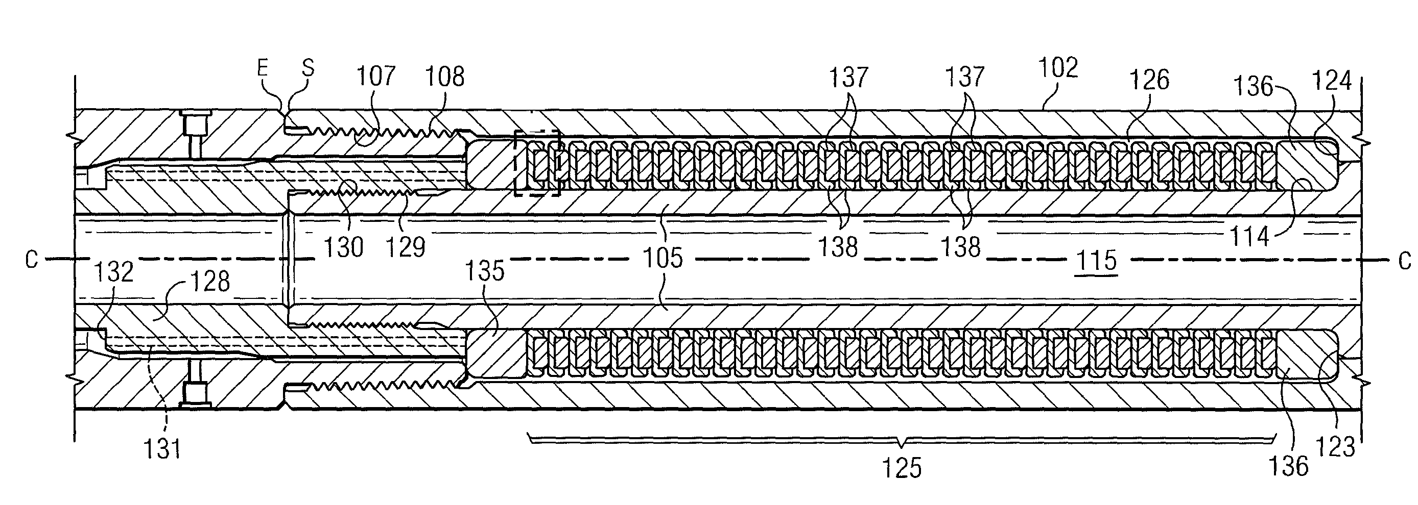
[0024]Parts, shown in the following drawings, toward the left of the drawings are referred to as down hole or forward parts as relating to the drilling direction. The back or up hole end of such parts is to the right.

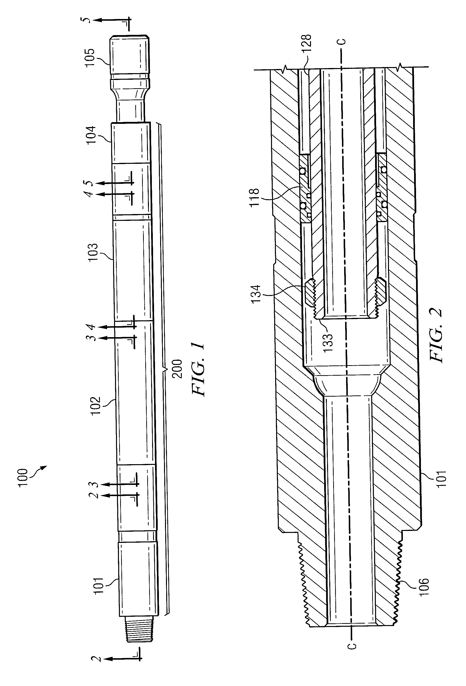
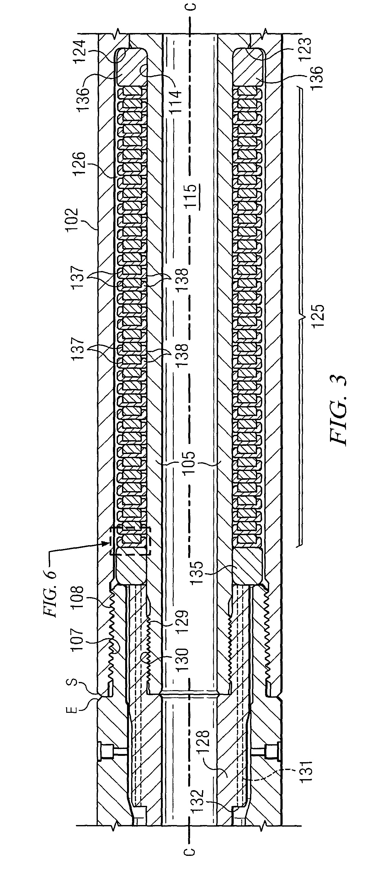
[0025]Referring first to FIG. 1, the vibration dampener 100 has a hollow generally cylindrical housing 200 made up of a bottom sub 101, a bowl 102, female hex housing 103, a seal carrier 104. The housing 200 is supported aroun...


PUM


Abstract

A down hole vibration dampener is disclosed that uses a set of polyurethane rings and steel support rings to create a shock absorber within the drill string to reduce the amount of vibration in the drill string. A splined mandrel extends longitudinally within a hollow cylindrical housing. A seal structure present between the exterior of the mandrel and the interior of the housing forms a lubricant receiving chamber. The series of polyurethane and steel rings are located in the lubricant chamber and are compressible longitudinally to absorb vibration and shock loads.

Description

CROSS-REFERENCE TO RELATED APPLICATIONS[0001]This application claims priority from a previously filed provisional application Ser. No. 61 / 145,863, filed Jan. 20, 2009, entitled “Down Hole Vibration Dampener”, by the same inventors.BACKGROUND OF THE INVENTION[0002]1. Field of the Invention[0003]This invention relates to a tool positionable in a drill string or stem which is useful for absorbing shock, vibration and impact loading otherwise imparted to the drill string during drilling operations.[0004]2. Description of the Prior Art[0005]When a well is being drilled, the vibration caused by the drill bit is substantial. In some cases, the vibration frequency caused by the drilling can reach the harmonic frequency of the drill string, which causes the drill bit to begin bouncing off of the bottom of the hole. This condition is called slip-stick. This condition is completely undesirable, and is harmful to the drill bit and the other tools of the drill string. These tools include such eq...

Claims


Application Information

Patent Timeline
Patent Type & Authority Patents(United States)
IPC IPC(8): E21B17/07
CPCE21B17/07
Inventor BOWAR, DAVID A.BLAIR, PARIS E.FICKEN, JOSEPH L.
Owner RIVAL DOWNHOLE TOOLS LC
Why Eureka
Try Eureka