Machining method of target material

A processing method and target material technology, which is applied in metal material coating process, ion implantation plating, coating, etc., can solve the problems that the target material processing quality needs to be improved.

Inactive Publication Date: 2018-01-12
合肥江丰电子材料有限公司
View PDF1 Cites 10 Cited by
  • Summary
  • Abstract
  • Description
  • Claims
  • Application Information

AI Technical Summary

Problems solved by technology

[0007] However, the processing quality of

Method used


Image

  • Machining method of target material
  • Machining method of target material
  • Machining method of target material

Examples


Embodiment Construction

[0030] It can be seen from the background art that the processing quality of the target material in the prior art needs to be improved. Analyze the reasons for this:

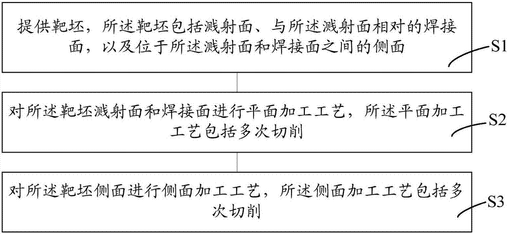
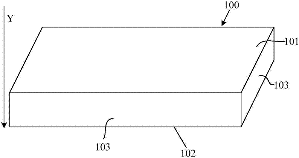
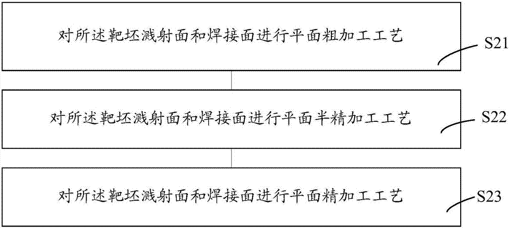
[0031] In the actual manufacturing process, it is necessary to process the sputtering surface, welding surface and side of the target blank, so as to improve the flatness and parallelism of the target blank, and match the size of the target with the structure of the sputtering equipment. During the sputtering process, the quality of the sputtered coating is improved.

[0032] However, during the processing, the target is subjected to the cutting force of the tool. In order to prevent deformation, the internal stress opposing the cutting force is released inside the material. The two forces are equal in magnitude and opposite in direction. to achieve a balance. After the processing is completed, the cutting force of the tool on the target disappears, the balance inside the target is broken, and the internal str...


PUM


Abstract

The invention provides a machining method of target material. The method comprises the following steps: providing a target blank comprising a sputtering surface, a welding surface opposite to the sputtering surface and a side surface located between the sputtering surface and the welding surface; performing plane machining operation on the sputtering surface of the target blank; and performing side-surface machining operation on the side surface of the target blank, wherein the plane machining operation and the side-surface machining operation both comprise cutting multiple times. During the plane machining operation and the side-surface machining operation, both the plane machining operation and the side-surface machining operation comprise cutting multiple times. The cutting frequency isincreased such that feeding amount and engagement of each cut are correspondingly reduced. Compared with the scheme with fewer cutting frequency, the machining method of target material can reduce cutting force of a tool to the target material during machining so that release of internal stress in the interior of the target material is minimized, thereby reducing the deformation degree of the target material. Additionally, reduction in cutting force can help vibration amount during machining of the target material, which further improves machining quality of the target material.

Description

technical field [0001] The invention relates to the field of semiconductor manufacturing, in particular to a target processing method. Background technique [0002] Liquid crystal display (LCD) has gradually replaced the traditional cathode ray tube (CRT) display with its advantages of no radiation, power saving, and small space, and has been widely used in various fields of production and life, such as computer monitors, notebook computers, Tablet PCs, mobile phones, TVs, monitoring equipment, industrial control instruments, etc. And according to statistics, liquid crystal displays are still growing by more than 10% per year to meet market demand. [0003] The metal target is one of the most important raw materials in the manufacture of liquid crystal displays. The physical vapor deposition process is generally used in the manufacture of liquid crystal displays. During the physical vapor deposition process, the argon ions formed by ionization are accelerated under the acti...

Claims


Application Information

Patent Timeline
IPC IPC(8): B23P15/00C23C14/34
Inventor 姚力军潘杰相原俊夫大岩一彦王学泽李健成
Owner 合肥江丰电子材料有限公司
Why Eureka
Try Eureka