

A1ZrCrN composite dual-gradient coating cutting tool and preparation method thereof
A dual-gradient, tool technology, applied in coatings, tools for lathes, metal material coating processes, etc., can solve wear, damage and even fracture, the performance difference between the coating and the tool matrix, and the reduction of tool life, etc. problems, to achieve the effect of improving comprehensive mechanical properties, reducing residual thermal stress, and smoothing coefficient of thermal expansion
- Summary
- Abstract
- Description
- Claims
- Application Information
AI Technical Summary
Problems solved by technology
Method used
Image

Examples
preparation example Construction
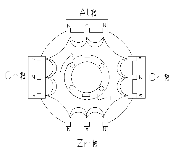
[0037] A method for preparing an A1ZrCrN composite double-gradient coating tool. Firstly, the tool substrate is ultrasonically cleaned, and then the tool substrate and the required target are placed in the vacuum chamber of a coating machine, and the tool substrate is glow-discharge cleaned and ion cleaned. After that, coating is carried out, and the coating process steps are as follows:
[0038] (1) Cr transition layer coating stage: After the vacuum chamber is evacuated, Ar gas is introduced to make the partial pressure of Ar gas in the vacuum chamber 0.4~0.6 Pa, and the bias voltage at both ends of the tool substrate is adjusted to 100~250 V. While adjusting the target current to 15A, turn on and maintain the Al target current of 0.4A and the Zr target current of 0.2A for 3.5-4.5min;
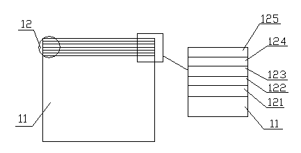
[0039] (2) Gradient CrN transition layer coating stage: pass N into the vacuum chamber 2 gas, and adjust the flow rate of Ar gas so that N 2 The partial pressure ratio of gas and Ar gas is ...
Embodiment 1
[0057] A method for preparing an A1ZrCrN compound double-gradient coating tool. Firstly, the tool substrate is ultrasonically cleaned, and then the tool substrate and the required target are placed in the vacuum chamber of a coating machine, and the tool substrate is glow-discharge cleaned and ion-cleaned. After that, coating is carried out, and the coating process steps are as follows:
[0058](1) Cr transition layer coating stage: After the vacuum chamber is evacuated, Ar gas is introduced to make the partial pressure of Ar gas in the vacuum chamber 0.4~0.6 Pa, and the bias voltage at both ends of the tool substrate is adjusted to 100~250 V. While adjusting the target current to 15A, turn on and maintain the Al target current of 0.4A and the Zr target current of 0.2A for 4 minutes;
[0059] (2) Gradient CrN transition layer coating stage: pass N into the vacuum chamber 2 gas, and adjust the flow rate of Ar gas so that N 2 The partial pressure ratio of gas and Ar gas is 1.5...
Embodiment 2
[0071] A method for preparing an A1ZrCrN composite double-gradient coating tool. Firstly, the tool substrate is ultrasonically cleaned, and then the tool substrate and the required target are placed in the vacuum chamber of a coating machine, and the tool substrate is glow-discharge cleaned and ion cleaned. After that, coating is carried out, and the coating process steps are as follows:
[0072] (1) Cr transition layer coating stage: After the vacuum chamber is evacuated, Ar gas is introduced to make the partial pressure of Ar gas in the vacuum chamber 0.4~0.6 Pa, and the bias voltage at both ends of the tool substrate is adjusted to 100~250 V. While adjusting the target current to 15A, turn on and maintain the Al target current of 0.4A and the Zr target current of 0.2A for 3.5-4.5min;
[0073] (2) Gradient CrN transition layer coating stage: pass N into the vacuum chamber 2 gas, and adjust the flow rate of Ar gas so that N 2 The partial pressure ratio of gas and Ar gas is ...
PUM
 Abstract
Description
Claims
Application Information