Hybrid drive unit and vehicle mounted therewith

a hybrid drive and drive unit technology, applied in the direction of electric propulsion mounting, transportation and packaging, gearing, etc., can solve the problems of negative impact on driver's drive feeling and generate resonance, and achieve the effect of reducing the vibration of an internal combustion engin

Active Publication Date: 2008-04-01
AISIN AW CO LTD +1
View PDF12 Cites 10 Cited by
  • Summary
  • Abstract
  • Description
  • Claims
  • Application Information

AI Technical Summary

Benefits of technology

[0010]It is an aspect of the invention to provide a hybrid drive unit that can improve the driver's drive feeling. In this hybrid drive unit, a mounting portion is provided between a hybrid mechanism and a transfer so that heavy structural members of the hybrid drive unit are positioned to front and rear sides of the mounting portion. Accordingly, the mounting portion is aligned with a nodal point of the bending vibration of the overall hybrid drive unit, and thus, vibration caused by the explosion stokes of the internal combustion engine is transmitted less easily to the vehicle body via the mounting portion.
[0011]According to a first aspect of the invention, a hybrid drive unit is provided with a hybrid mechanism and a transfer. The hybrid mechanism includes at least one electric motor that is a heavy structural member of the hybrid drive unit, and furthermore, the transfer itself is also a heavy structural member. The electric motor and the transfer are positioned separately to the front and rear of a first mounting portion, thereby making it possible to align the first mounting portion with a nodal point of bending vibration of the overall hybrid drive unit. By adopting this configuration, it is possible to inhibit vibration caused by explosion strokes of an internal combustion engine from being transmitted to a vehicle body through the first mounting portion. Accordingly, the driver's driving feeling is improved.
[0012]Moreover, according to a second aspect of the invention, a speed change unit is positioned in a forward direction from the first mounting portion, and the electric motor which is a heavy structural member is positioned further in the forward direction from the speed change unit. As a result of adopting this configuration, it is possible to further reduce the amount of vibration of the internal combustion engine that is transmitted to the vehicle body through the first mounting portion.
[0017]According to a sixth aspect of the invention, it is possible to reduce the amount of vibration of an internal combustion engine that is transmitted to a vehicle body of an automobile through a hybrid drive unit.

Problems solved by technology

However, if this configuration is adopted, resonance is generated by the frequency of vibrations caused by the explosion strokes of the internal combustion engine overlapping with the frequency of bending vibration of the overall hybrid drive unit.
Accordingly, the vibrations are amplified and transmitted to the vehicle body, whereby the driver's drive feeling is detrimentally affected.

Method used


Image

  • Hybrid drive unit and vehicle mounted therewith
  • Hybrid drive unit and vehicle mounted therewith
  • Hybrid drive unit and vehicle mounted therewith

Examples


first embodiment

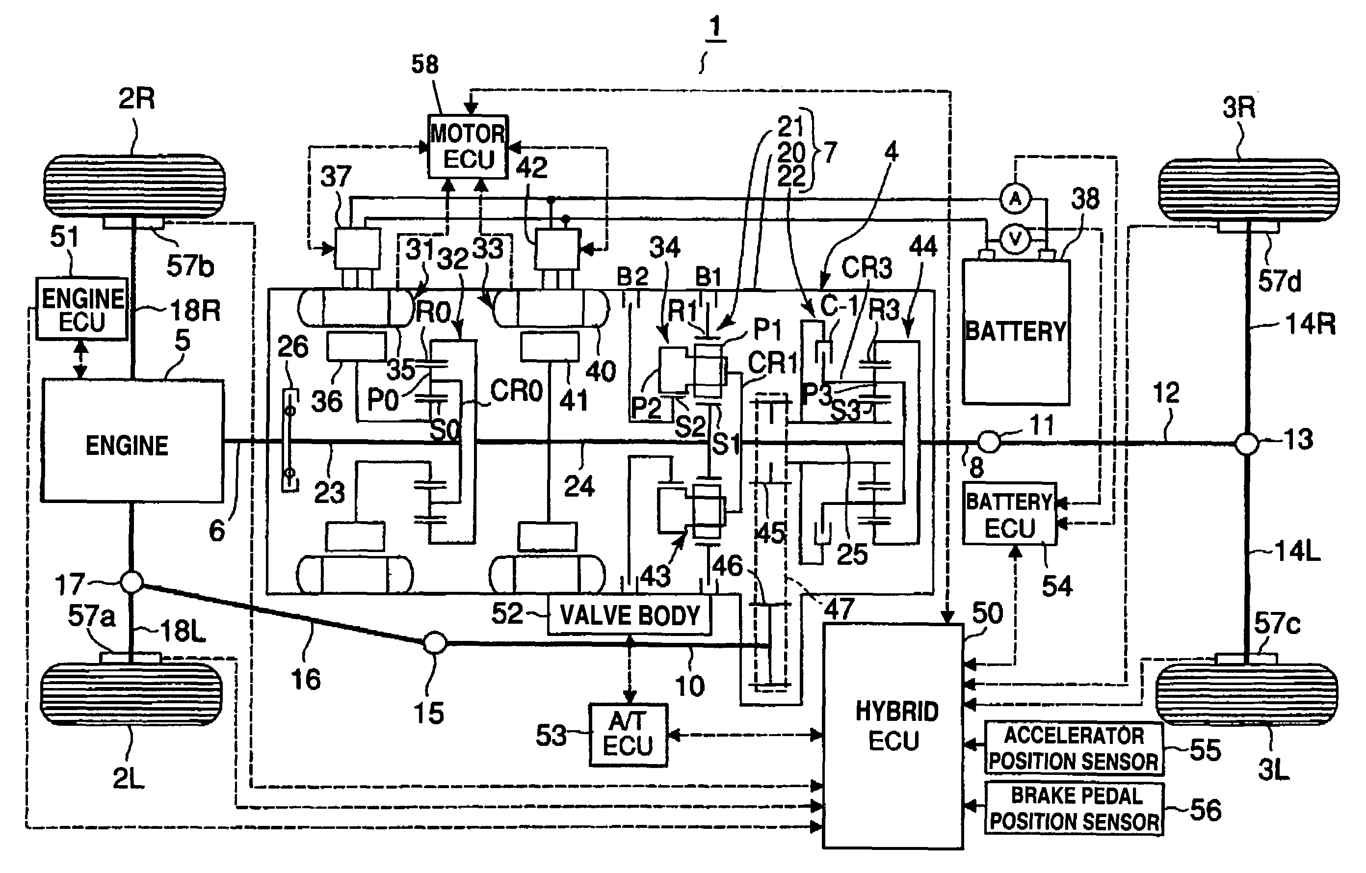
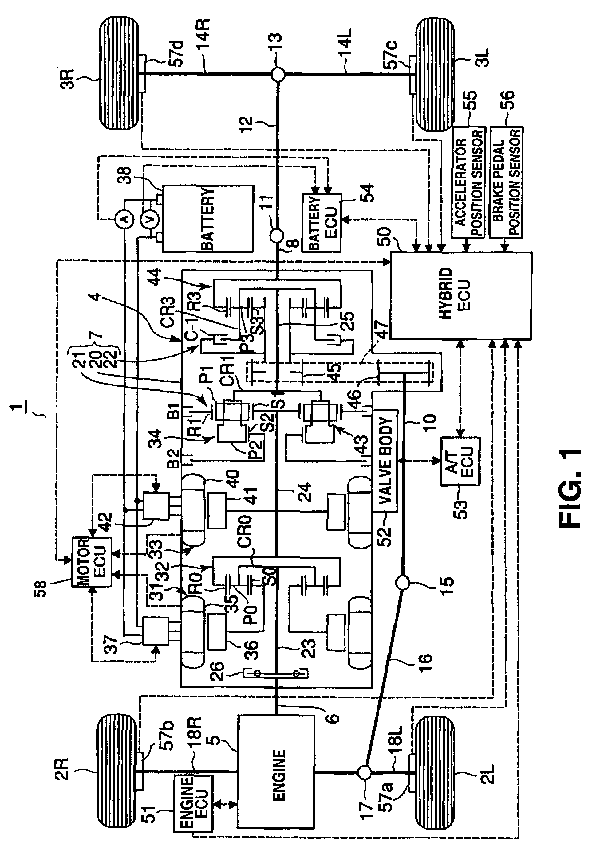
[0021]FIG. 1 shows an example of a vehicle according to the invention, and, more specifically, shows a vehicle 1 in which a hybrid drive unit according to the invention is mounted. The illustrated vehicle 1 is a four-wheel drive vehicle, and is shown, in FIG. 1, in a figure that combines a skeleton figure of the hybrid drive unit with a schematic outline view of the vehicle 1 when viewed from above. Note that, if the vehicle 1 was an actual vehicle, the end of the vehicle 1 at the left-hand side of FIG. 1 would be the front, and the end of the vehicle 1 at the right-hand side would be the rear. Further, in this specification, the front and rear, the top and bottom, and the left and right of the hybrid drive unit are defined based on the position in which the hybrid drive unit is mounted in a body 4 of the vehicle 1.

[0022]First, an outline of the configuration and the operation of the vehicle 1 will be explained with reference to FIG. 1.

[0023]As shown in FIG. 1 the body 4 of the vehi...


PUM


Abstract

A hybrid drive unit includes a hybrid mechanism having at least one electric motor and a transfer that distributes driving force to front and rear wheels. The electric motor and the transfer are housed in a tubular shaped transmission case that extends in the front and rear directions of a vehicle. The hybrid drive unit is mounted on and supported by a second attachment coupled to an internal combustion engine and provided at a front end of the hybrid drive unit and a first attachment portion fixed to a vehicle body. The electric motor and the transfer that are heavy structural members of the hybrid drive unit are positioned separately to the front and rear of the first attachment portion that forms a boundary. By adopting this configuration, it is possible to reduce the amount of engine vibration that is transmitted to the vehicle body through the first attachment portion.

Description

BACKGROUND OF THE INVENTION[0001]The disclosure of Japanese Patent Application No. 2003-403667 filed on Dec. 2, 2003, including the specification, drawings and abstract is incorporated herein by reference in its entirety.[0002]1. Field of the Invention[0003]The invention relates to a hybrid drive unit that can be mounted in a vehicle, and a vehicle in which this hybrid drive unit is mounted. More particularly, the invention relates to a hybrid drive unit having a transfer that distributes driving force to front and rear wheels of a vehicle, and a vehicle provided with the same hybrid drive unit.[0004]2. Description of the Related Art[0005]A front-engine rear-drive (FR) hybrid vehicle includes a hybrid drive unit which is mounted to the rear of the engine and which acts as a transmission.[0006]The hybrid drive unit includes a tubular shaped transmission case (case member) that extends in a front-rear direction, as well as an input shaft, an output shaft, and a hybrid mechanism that a...

Claims


Application Information

Patent Timeline
Patent Type & Authority Patents(United States)
IPC IPC(8): B60K6/00B60K1/02B60K6/24B60K6/26B60K6/36B60K6/365B60K6/40B60K6/405B60K6/445B60K6/52B60K6/547B60K17/04B60K17/06B60K17/344B60K17/346B60L50/16F16H3/72
CPCB60K6/365B60K6/405B60K6/445B60K6/52B60K1/02F16H3/728F16H2037/0873F16H2200/201F16H2200/2023Y02T10/6265Y02T10/6239Y10S903/911Y02T10/62
Inventor TAKAMI, SHIGEKIMIURA, KIYOTOMOWAKUTA, SATORUOZAKI, KAZUHISA
Owner AISIN AW CO LTD
Why Eureka
Try Eureka