Electrical connector system with orthogonal contact tails

a technology of connectors and tails, applied in the direction of fixed connections, coupling device connections, coupling protective earth/shielding arrangements, etc., can solve the problems of limiting the available channels for trace routing on the midplane pcb, limiting the spacing between, and not allowing electrical connection of connector contacts. , to achieve the effect of convenient routing

Active Publication Date: 2012-08-28
FCI AMERICAS TECH LLC
View PDF23 Cites 93 Cited by
  • Summary
  • Abstract
  • Description
  • Claims
  • Application Information

AI Technical Summary

Benefits of technology

[0005]Disclosed are electrical connectors and methods of assembling an electrical connector having “standard” (i.e., with electrical contacts having in-line tails), jogged (i.e., with electrical contacts having jogged tails but not connected orthogonally to another connector through a substrate), and / or “orthogonal” (i.e., with electrical contacts having jogged tails that are used in an orthogonal application) leadframe assemblies in the same connector. This provides the flexibility of using some of the available contacts in an orthogonal application and, at the same time, having remaining contacts available for routing on the midplane PCB. Though this could be done using only orthogonal leadframe assemblies, the combination of standard leadframe assemblies with orthogonal leadframe assemblies creates additional spacing between the PCB vias, so that signal traces can be more easily routed on the midplane PCB.

Problems solved by technology

However, this configuration may not allow for electrical connection of a connector contact to trace routing on the midplane PCB.
This configuration may limit the spacing between the PCB vias, which may limit the available channels for trace routing on the midplane PCB.

Method used


Image

  • Electrical connector system with orthogonal contact tails
  • Electrical connector system with orthogonal contact tails
  • Electrical connector system with orthogonal contact tails

Examples


second embodiment

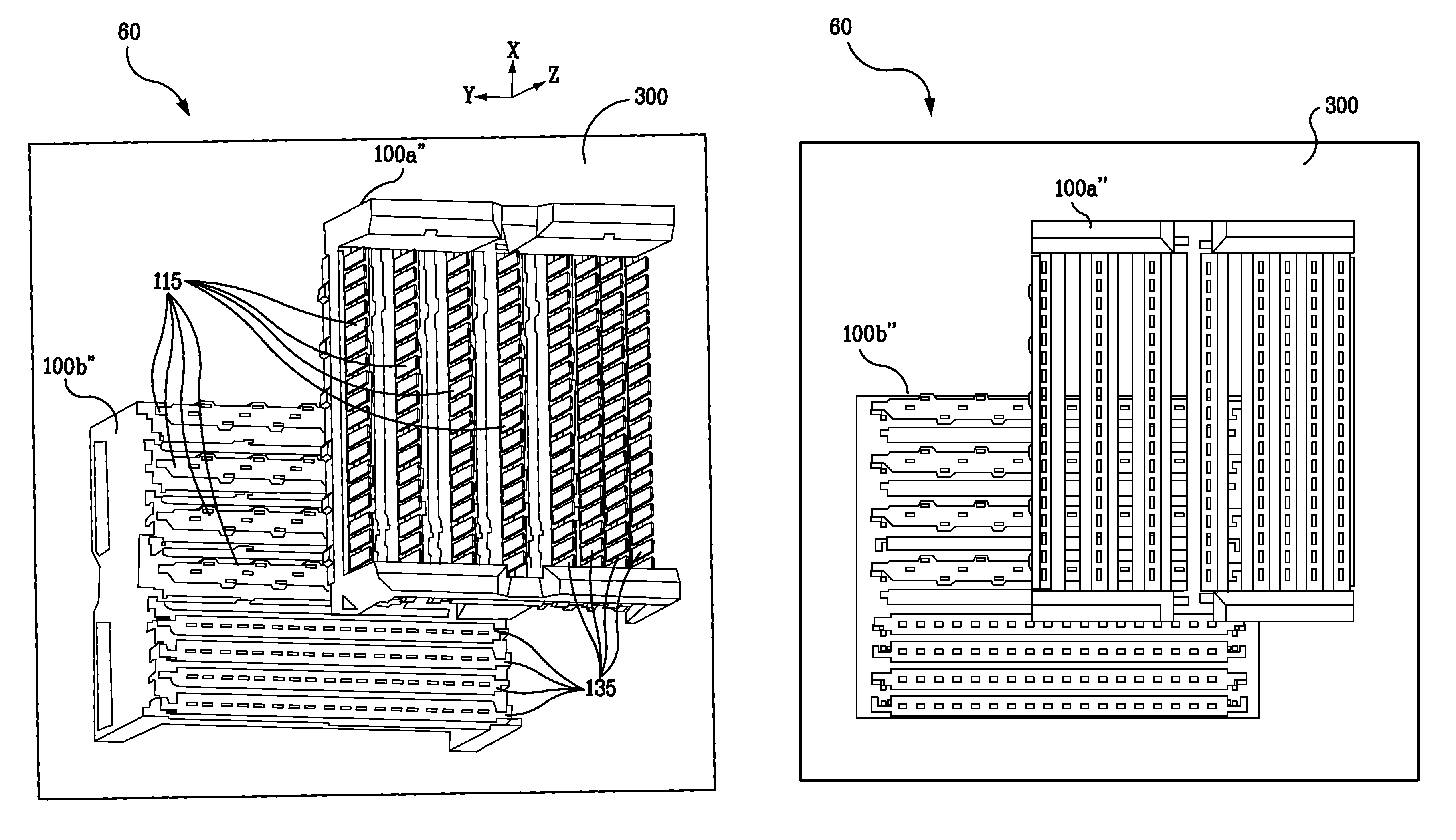
[0083]FIG. 10 depicts a pin-out diagram of the midplane for the mounted connector pair, wherein a 4×4 orthogonal connector is electrically connected to a 6×6 mixed connector. FIG. 10, which is shown from the view of first side 301 of midplane 300, shows the details of the electrical mating between the orthogonal columns of contact tails 120a, 120b, 120c, and 120d of mixed leadframe connector 100 and the orthogonal columns of contact tails 220a, 220b, 220c, and 220d of orthogonal leadframe connector 200. FIG. 10 shows sixteen (16) pairs of signal contact tails 123 from mixed leadframe connector 100 mated with the corresponding sixteen pairs of signal contact tails 223 from orthogonal leadframe connector 200. Also shown in FIG. 10 are two standard columns of contact tails 140a and 140b of mixed leadframe connector 100, which, in this embodiment, are not electrically connected to corresponding contact tails of orthogonal leadframe connector 200.

[0084]This second embodiment, electrical ...

first embodiment

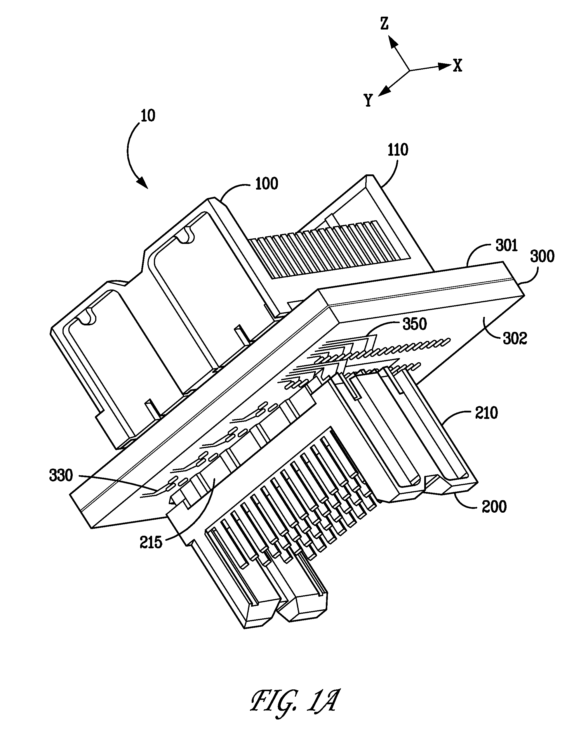
[0085]In FIG. 10, the two standard columns of contact tails 140 within leadframe housing 110 are at opposite ends of leadframe housing 110, with the four orthogonal columns of contact tails 120 between the two standard columns of contact tails 140. Accordingly, the two standard columns of vias 340 in midplane 300 are at opposite ends of midplane 300, with the orthogonal pattern of vias 320 positioned in between the two standard columns of vias 340. As in the first embodiment electrical connector system 10, orthogonal leadframe connector 200 mates with mixed leadframe connector 100 through shared vias in midplane 300, but in electrical connector system 20, orthogonal leadframe connector 200 is approximately centered in the X-Y plane (as shown by the arrows designated X and Y in FIG. 1A) relative to mixed leadframe connector 100, wherein the sixteen (16) pairs of signal contact tails 223 in connector 200 mate with the 16 pairs of signal contact tails 123 in the center of mixed leadfra...

third embodiment

[0096]FIG. 11B depicts a pin-out diagram of the midplane for the third embodiment depicted in FIG. 11A. FIG. 11B, which is shown from the view of first side 301 of midplane 300, shows the details of the electrical mating between the orthogonal columns of contact tails 120a, 120b, 120c, and 120d of orthogonal leadframe connector 100′ and the orthogonal columns of contact tails 220a, 220b, 220c, and 220d of orthogonal leadframe connector 200. FIG. 11B shows sixteen (16) pairs of signal contact tails 123 from mixed leadframe connector 100′ mated with the corresponding sixteen pairs of signal contact tails 223 from orthogonal leadframe connector 200. Also shown in FIG. 11B are two additional orthogonal columns of contact tails 120e and 120f of orthogonal leadframe connector 100′, which, in this embodiment, are not electrically connected to corresponding contact tails of orthogonal leadframe connector 200.

[0097]Comparing FIGS. 9 and 11B, the difference between the first embodiment (elect...


PUM

PropertyMeasurementUnit
metallicaaaaaaaaaa
dielectricaaaaaaaaaa
electrically conductiveaaaaaaaaaa

Abstract

Disclosed are electrical connectors and methods of assembling an electrical connector having “standard” (i.e., with electrical contacts having in-line tails), jogged (i.e., with electrical contacts having jogged tails but not connected orthogonally to another connector through a substrate), and / or “orthogonal” (i.e., with electrical contacts having jogged tails that are used in an orthogonal application) leadframe assemblies in the same connector. This provides the flexibility of using some of the available contacts in an orthogonal application and, at the same time, having remaining contacts available for routing on the midplane PCB. Though this could be done using only orthogonal leadframe assemblies, the combination of standard leadframe assemblies with orthogonal leadframe assemblies creates additional spacing between the PCB vias, so that signal traces can be more easily routed on the midplane PCB.

Description

CROSS-REFERENCE TO RELATED APPLICATIONS[0001]This application claims benefit under 35 U.S.C. §119(e) of provisional U.S. patent application No. 60 / 986,223, filed Nov. 7, 2007, the contents of which are incorporated herein by reference in their entirety.FIELD OF THE INVENTION[0002]Generally, the invention relates to electrical connectors. More particularly, the invention relates to connector applications wherein orthogonally-mated connectors share common vias through a midplane. The invention further relates to electrical connectors incorporating different sized connectors on each side of a midplane.BACKGROUND OF THE INVENTION[0003]Electrical connectors may be used in orthogonal applications. In an orthogonal application, each of two connectors is mounted to a respective, opposite side of a so-called “midplane.” The connectors are electrically coupled to one another through the midplane. A pattern of electrically conductive vias may be formed through the midplane. The terminal mounti...

Claims


Application Information

Patent Timeline
Patent Type & Authority Patents(United States)
IPC IPC(8): H01R13/648
CPCH01R13/6471H01R13/6477H01R12/51H01R12/7082H01R12/71H01R13/514H05K1/0245H05K1/116H05K3/325H05K2201/09409Y10T29/49222H05K2201/10189H05K2201/1059H05K2201/09418
Inventor JOHNESCU, DOUGLAS M.MINICH, STEVEN E.SMITH, STEPHEN B.
Owner FCI AMERICAS TECH LLC
Why Eureka
Try Eureka