
Optical tomography system with high-speed scanner

a tomography system and high-speed technology, applied in the field of high-speed focal plane scanners for optical projection tomography, can solve the problem of limited speed of the focal plane moving through the specimen

Inactive Publication Date: 2012-08-28
VISIONGATE
View PDF128 Cites 34 Cited by
  • Summary
  • Abstract
  • Description
  • Claims
  • Application Information

AI Technical Summary

Problems solved by technology

By using a PZT actuator to move the objective lens, a focal plane moving through the specimen has its speed limited by inertia inherent in moving the objective lens rapidly along the optical axis through the specimen.

Method used


Image

  • Optical tomography system with high-speed scanner
  • Optical tomography system with high-speed scanner
  • Optical tomography system with high-speed scanner

Examples


Embodiment Construction

[0015]The following disclosure describes several embodiments and systems for imaging an object of interest. Several features of methods and systems in accordance with example embodiments of the invention are set forth and described in the Figures. It will be appreciated that methods and systems in accordance with other example embodiments of the invention can include additional procedures or features different than those shown in Figures. Example embodiments are described herein with respect to biological cells. However, it will be understood that these examples are for the purpose of illustrating the principals of the invention, and that the invention is not so limited.

[0016]Additionally, methods and systems in accordance with several example embodiments of the invention may not include all of the features shown in these Figures. Throughout the Figures, like reference numbers refer to similar or identical components or procedures.

[0017]Unless the context requires otherwise, through...


PUM


Abstract

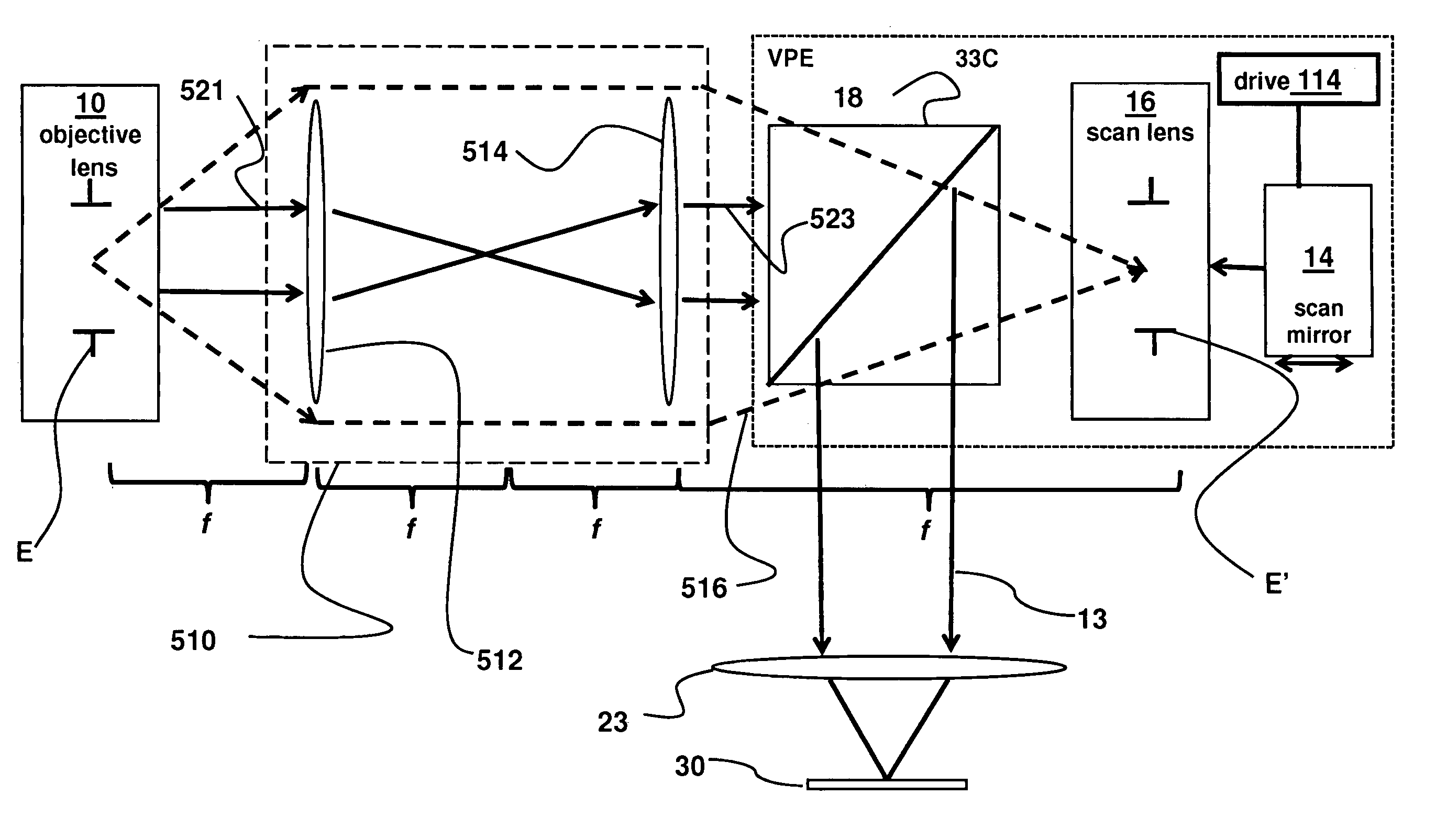
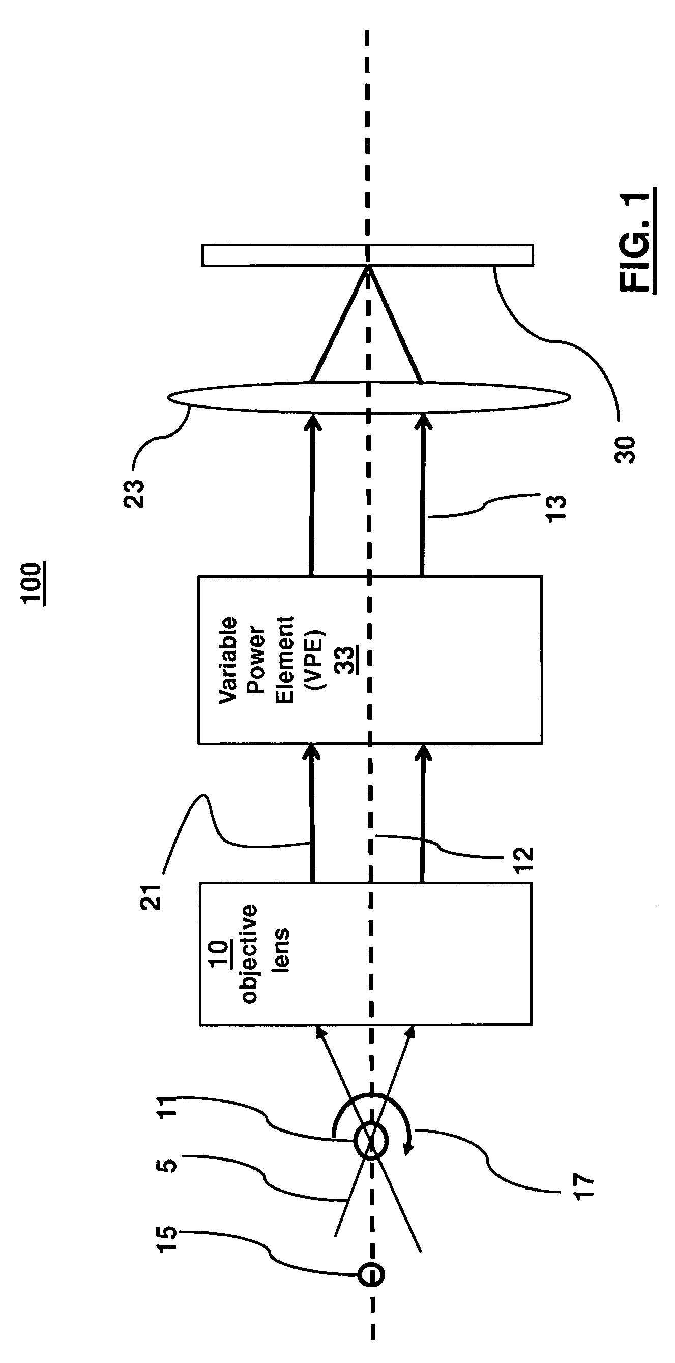
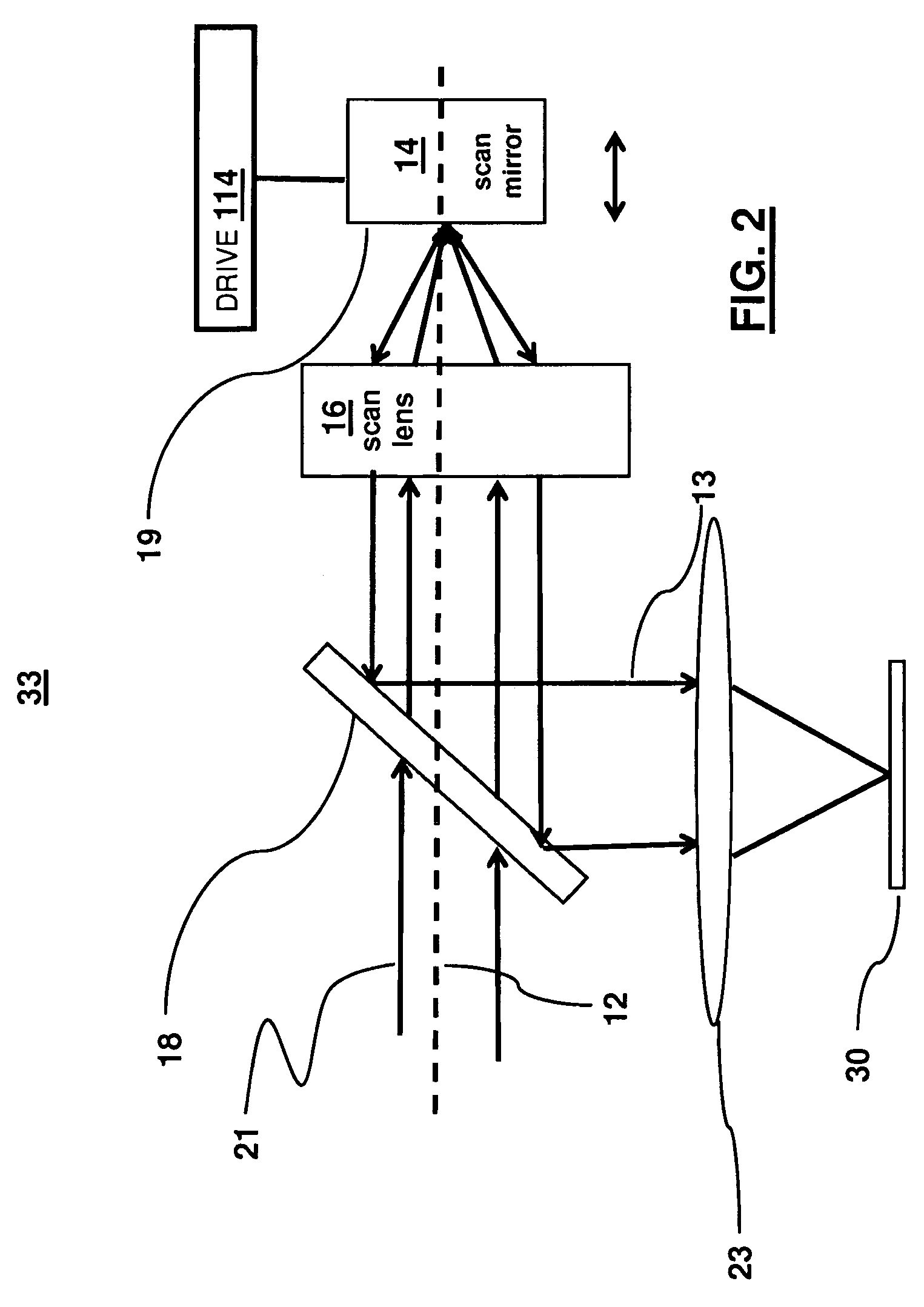
An object of interest is illuminated within the field of view of a microscope objective lens located to receive light passing through the object of interest. Light transmitted through the microscope objective lens impinges upon a variable power element. The variable power element is driven with respect to the microscope objective lens to scan through multiple focal planes in the object of interest. Light transmitted from the variable power element is sensed by a sensing element or array.

Description

TECHNICAL FIELD[0001]The present invention relates to optical tomographic imaging systems in general, and, more particularly, to a high-speed focal plane scanner for optical projection tomography, in which a small object, such as a biological cell, is imaged by a microscope.BACKGROUND[0002]Recently advances in imaging biological cells using optical tomography invented by A. C. Nelson have been disclosed, for example, in U.S. Pat. No. 6,522,775, issued Feb. 18, 2003, and entitled “Apparatus And Method For Imaging Small Objects In A Flow Stream Using Optical Tomography,” the full disclosure of which is incorporated by reference. Further developments in the field are taught in Fauver et al., U.S. Pat. No. 7,738,945 issued on Jun. 15, 2010, entitled “Method And Apparatus Of Shadowgram Formation For Optical Tomography,” and Fauver et al., U.S. Pat. No. 7,907,765, issued on Mar. 15, 2011, entitled “Focal Plane Tracking For Optical Microtomography,” the full disclosures of which are also i...

Claims


Application Information

Patent Timeline
Patent Type & Authority Patents(United States)
IPC IPC(8): G02B23/14G02B21/00
CPCG02B21/002G01N21/4795G02B21/025G02B27/0075
Inventor WATSON, MATHEW D.HAYENGA, JON W.
Owner VISIONGATE
Learn More