Measurement apparatus
a technology of measurement apparatus and spectroscopic characteristic, which is applied in the field of measurement apparatus, can solve the problems of inability to provide the metabolism calorie of the measurement site that is a local area in the tissue, the method is complicated, and the calculation method is huge, so as to achieve high precision and easy to measure the local absorption-scattering
- Summary
- Abstract
- Description
- Claims
- Application Information
AI Technical Summary
Benefits of technology
Problems solved by technology
Method used
Image
Examples
first embodiment
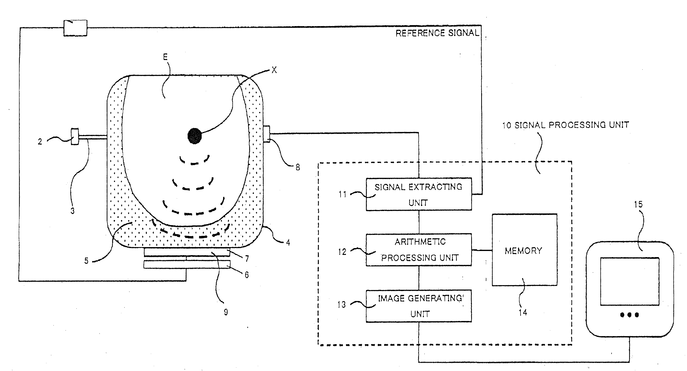
[0022]FIG. 1 is a block diagram of an AOT measurement apparatus 100 according to a first embodiment of the present invention. The measurement apparatus 100 is configured to measure an absorption-scattering characteristic in the biological tissue of the specimen E using the AOT, and includes a measurement unit, a signal processing device 10, and a display device 15.
[0023]The specimen E has a biological tissue, such as a breast, and also an absorption-scattering body.
[0024]The measurement unit includes a sinusoidal oscillator 1, a light source 2, an optical fiber 3, a measurement vessel 4, a matching material 5, an ultrasound oscillator (an ultrasound transducer array) 6, an ultrasound focusing device 7, and a light detector (detecting device) 8.
[0025]The sinusoidal oscillator 1 drives the ultrasound generating device 6 at a sinusoidal signal of a frequency f.
[0026]The light source 2 is a light source configured to generate the luminous fluxes having a plurality of wavelengths to be i...
second embodiment
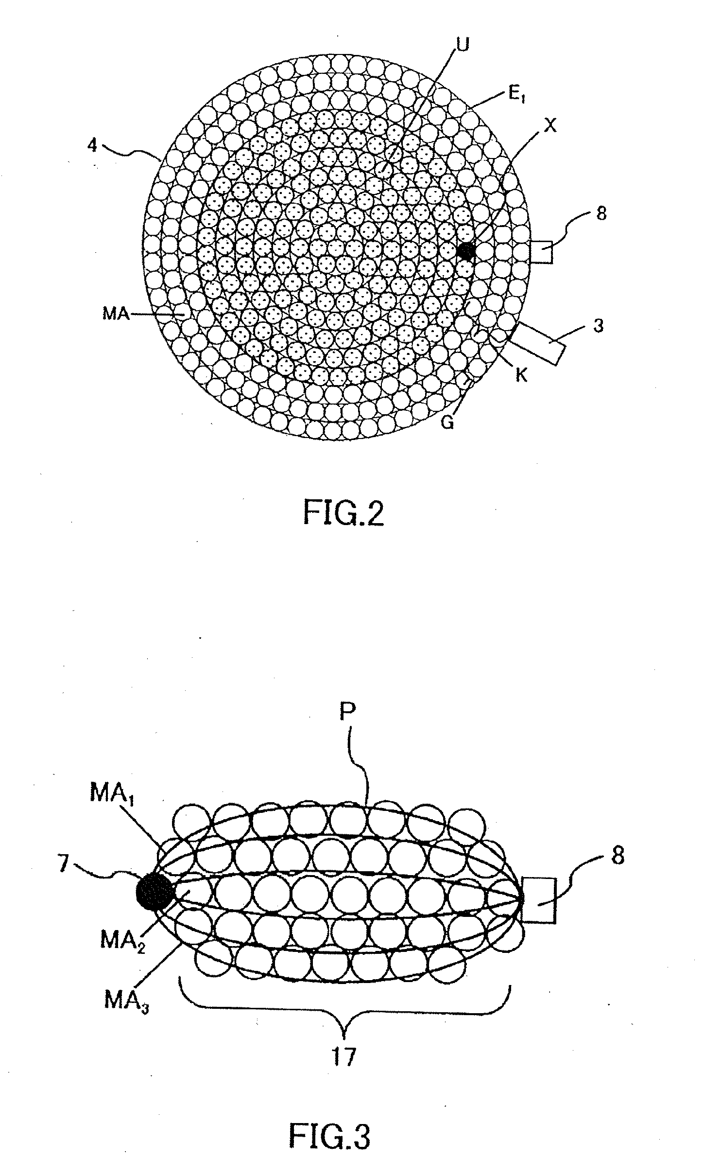
[0061]The second embodiment also uses the measurement apparatus 100 shown in FIG. 1. The first embodiment measures and calculates the absorption-scattering characteristic on a real-time basis. On the other hand, the second embodiment measures and obtains the measurement data, and then the signal processing device 10 calculates an absorption-scattering characteristic. The second embodiment measures similarly to the first embodiment, but does not limit the measurement order, as long as the measurement areas MA and the measurement site X are set in the entire area as shown in FIG. 2 and their measurement values exist. The memory 14 stores the light intensities of all measurement areas MA measured by the measurement unit before the processing unit 12 starts processing.
[0062]In measurement, the memory 14 stores the non-modulated light's intensity I1 (ri,θj) and the modulated light's intensity I2(ri,θj) measured at the position (ri,θj) of the measurement site X, and the measurement condit...
third embodiment
[0068]FIG. 8 is a block diagram of a PAT measurement apparatus 100A according to the third embodiment of the present invention. The measurement apparatus 100A uses the PAT to measure the spectroscopic characteristic (the absorption characteristic and the scattering characteristic) in the tissue of the specimen E, and includes the measurement unit, the light detector 8, a delay circuit 23, a signal processing device 24, a processing unit 26, the memory 14, and the display device 15. Those elements in FIG. 8, which are the corresponding elements in FIG. 1, will be designated by the same reference numerals and a description thereof will be omitted. The measurement unit has a light source 20, an optical fiber 21, and an ultrasound detecting device (an ultrasonic transducer array) 22.
[0069]The pulsed light is emitted from the light source 20, and enters the specimen E via the optical fiber 21. The energy absorbed in the specimen E is transformed into heat, and induces an elastic wave N t...
PUM
 Abstract
Description
Claims
Application Information
 - R&D
- Intellectual Property
- Life Sciences
- Materials
- Tech Scout
- Unparalleled Data Quality
- Higher Quality Content
- 60% Fewer Hallucinations
Browse by: Latest US Patents, China's latest patents, Technical Efficacy Thesaurus, Application Domain, Technology Topic, Popular Technical Reports.
© 2025 PatSnap. All rights reserved.Legal|Privacy policy|Modern Slavery Act Transparency Statement|Sitemap|About US| Contact US: help@patsnap.com


