Method and Apparatus for Improving Image Clarity and Sensitivity in Optical Tomography Using Dynamic Feedback to Control Focal Properties and Coherence Gating

a dynamic feedback and focal property technology, applied in the field of optical imaging, can solve the problems of signal to noise ratio, sensitivity decrease, and variability of the distance between the probe tip and the surface, and achieve the effect of moving much faster and more accurately, accurately determining the distance variation between the probe and the tissue surfa

Inactive Publication Date: 2011-08-18
THE GENERAL HOSPITAL CORP
View PDF104 Cites 61 Cited by
  • Summary
  • Abstract
  • Description
  • Claims
  • Application Information

AI Technical Summary

Benefits of technology

[0007]The present invention provides a time delay scanning unit as described herein. The present invention also provides a focus adjusting mechanism for an optical scanning system. The present invention also provides a method of time delay scanning to more accurately determine probe to tissue surface distance variations due to surface topography and probe length / design.
[0008]The present invention provides a rocking mirror, as one of several novel mechanisms, to create the delay line. A rocking mirror can be moved much faster and more accurately to retain synchronicity with the computer and the scanning probe. The present invention provides an algorithm to determine position to determine the changes to the galvanometric DC offset angle to conform to tissue distance from the probe tip. In addition, the present invention provides dynamic active feedback to alter the galvanometric AC angle to adjust the coherence gate scan depth to contain only useful image information. Finally, the present invention also is capable of using dynamic active feedback to adjust the focusing properties of the catheter (focal length, spot size, and confocal parameter).

Problems solved by technology

However, the surface of the wall may vary in topography or geometry, resulting in the variance of the distance between the probe tip and the surface.
Since conventional OCT imaging uses a fixed waveform to create the incident light beam in a schematically rectangular “window” of a certain height, the variation in surface height of the wall may result in the failure to gather tissue data in certain regions of the blood vessel wall.
The problem with this is that the signal to noise ratio and accompanying sensitivity decrease because one is collecting information over a larger area in the same amount of time.

Method used


Image

  • Method and Apparatus for Improving Image Clarity and Sensitivity in Optical Tomography Using Dynamic Feedback to Control Focal Properties and Coherence Gating
  • Method and Apparatus for Improving Image Clarity and Sensitivity in Optical Tomography Using Dynamic Feedback to Control Focal Properties and Coherence Gating
  • Method and Apparatus for Improving Image Clarity and Sensitivity in Optical Tomography Using Dynamic Feedback to Control Focal Properties and Coherence Gating

Examples


Embodiment Construction

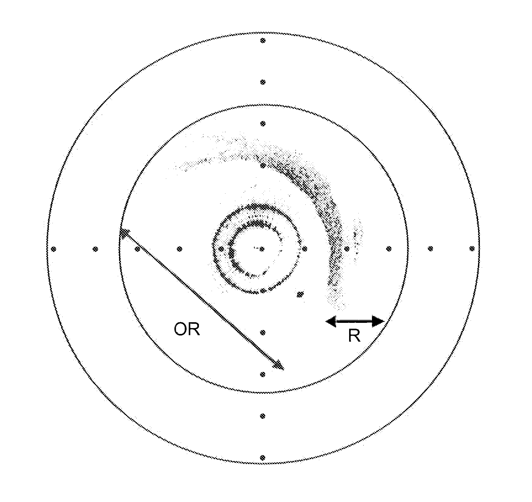
Offset and Scan Depth Control

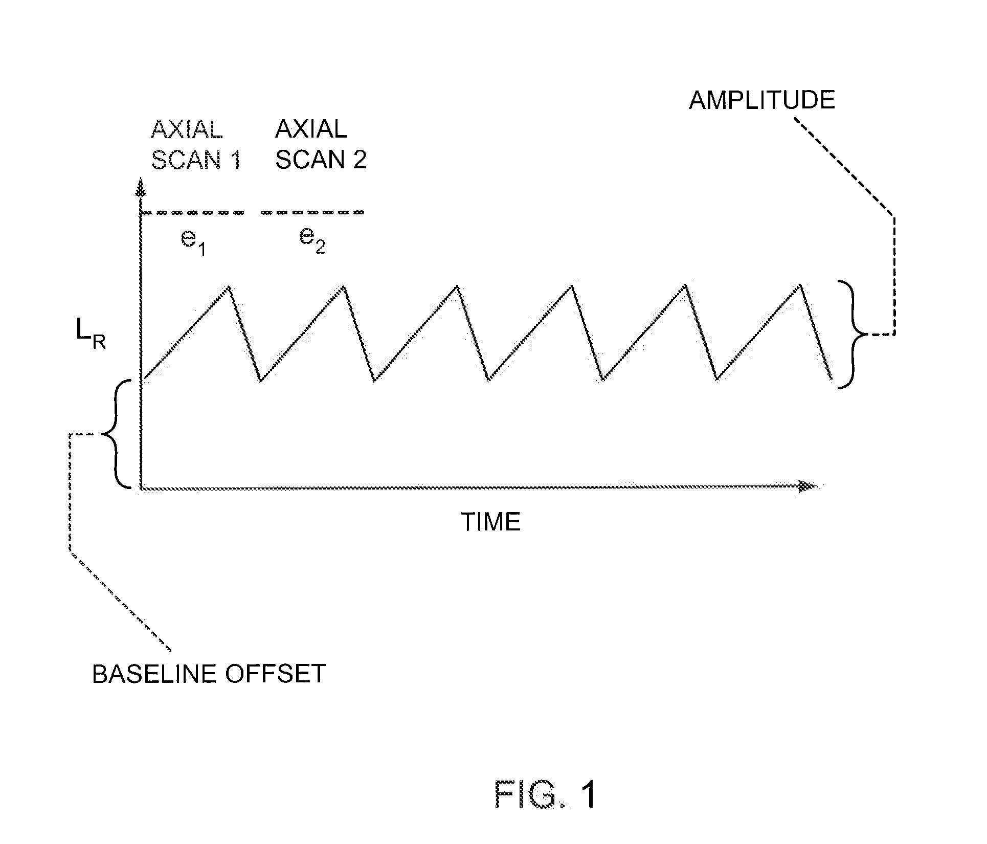
[0044]FIG. 1 is a graph of a seradyne waveform of a conventional DC baseline offset, where LR is the reference arm optical delay distance offset and t is time (e.g., 0-20 kHz). One scan image length is shown as “e1” and a second is shown as “e2”. The peak-to-peak amplitude is called the AC component.

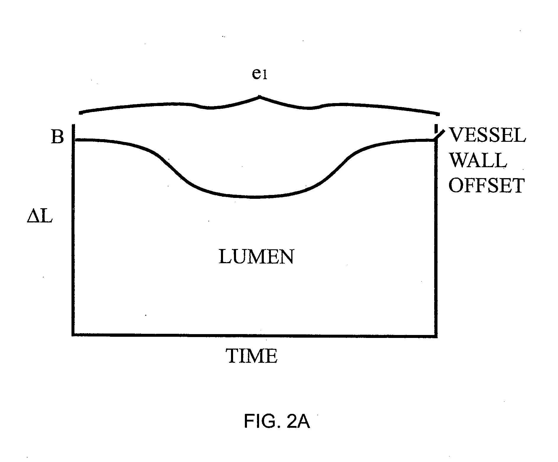
[0045]FIG. 2A shows a graph of the vessel wall offset contour of one contour scan waveform where the x-axis is time and the y-axis is ΔL. FIG. 2B shows the normal (constant offset) scanning wave of ΔLR which is a seradyne wave and is shown in where each period is a single scan image (shown as bracketed Axial Scan 1 having a scan image length of e1 and Axial Scan 2 having a scan image length of e2). In a given contour there can be somewhere in the range of 250-500 seradyne scans. FIG. 2A shows the offset correction for a period of a single scan. Optical delay (ΔL) is calculated as

ΔL=ΔLS−ΔLR

where ΔLS is the distance of the sample arm to the tissue surface and ...


PUM

PropertyMeasurementUnit
structureaaaaaaaaaa
transverse dimensionaaaaaaaaaa
focal distanceaaaaaaaaaa

Abstract

Methods for optical imaging, particularly with optical coherence tomography, using a low coherence light beam reflected from a sample surface and compared to a reference light beam, wherein real time dynamic optical feedback is used to detect the surface position of a tissue sample with respect to a reference point and the necessary delay scan range. The delay is provided by a tilting/rotating mirror actuated by a voltage adjustable galvanometer. An imaging probe apparatus for implementing the method is provided. The probe initially scans along one line until it finds the tissue surface, identifiable as a sharp transition from no signal to a stronger signal. The next time the probe scans the next line it adjusts the waveform depending on the previous scan. An algorithm is disclosed for determining the optimal scan range.

Description

CROSS-REFERENCE TO RELATED APPLICATION[0001]The present application claims priority from copending provisional application No. 60 / 287,477, filed Apr. 30, 2001, and commonly assigned to the assignee of the present application, and which is incorporated herein in its entirety.FIELD OF THE INVENTION[0002]The present invention relates to methods for optical imaging using a low coherence light beam reflected from a sample surface and compared to a reference light beam, wherein real time dynamic optical feedback is used to detect the surface position of a tissue sample with respect to a reference point and the necessary delay scan range. The present also relates to an imaging probe apparatus for implementing the method.BACKGROUND[0003]Optical coherence tomography is an imaging technique that measures the interference between a reference beam of light and a detected beam of light that has impinged on a target tissue area and been reflected by scatterers within tissue back to a detector. In...

Claims


Application Information

Patent Timeline
Patent Type & Authority Applications(United States)
IPC IPC(8): A61B6/00A61B5/00G01B9/02G01N21/47
CPCA61B5/0066A61B5/0068A61B5/0084A61B5/6852A61B5/6853G01B2290/35G01B9/02085G01B9/0205G01B9/02091G01B9/02063G01B9/02068G01N21/4795
Inventor TEARNEY, GUILLERMO J.BOUMA, BRETT EUGENE
Owner THE GENERAL HOSPITAL CORP
Why Eureka
Try Eureka