Focal Plane Tracking for Optical Microtomography

a technology of optical microtomography and tracking plane, which is applied in the field of microscopic optical tomography, can solve the problems of focusing errors and adversely affecting the post-image acquisition reconstruction of specimens

Active Publication Date: 2010-12-23
VISIONGATE +1
View PDF54 Cites 56 Cited by
  • Summary
  • Abstract
  • Description
  • Claims
  • Application Information

AI Technical Summary

Problems solved by technology

Such offset positions can cause focusing errors and adversely affect post-imaging acquisition reconstruction of the specimen.

Method used


Image

  • Focal Plane Tracking for Optical Microtomography
  • Focal Plane Tracking for Optical Microtomography
  • Focal Plane Tracking for Optical Microtomography

Examples


Embodiment Construction

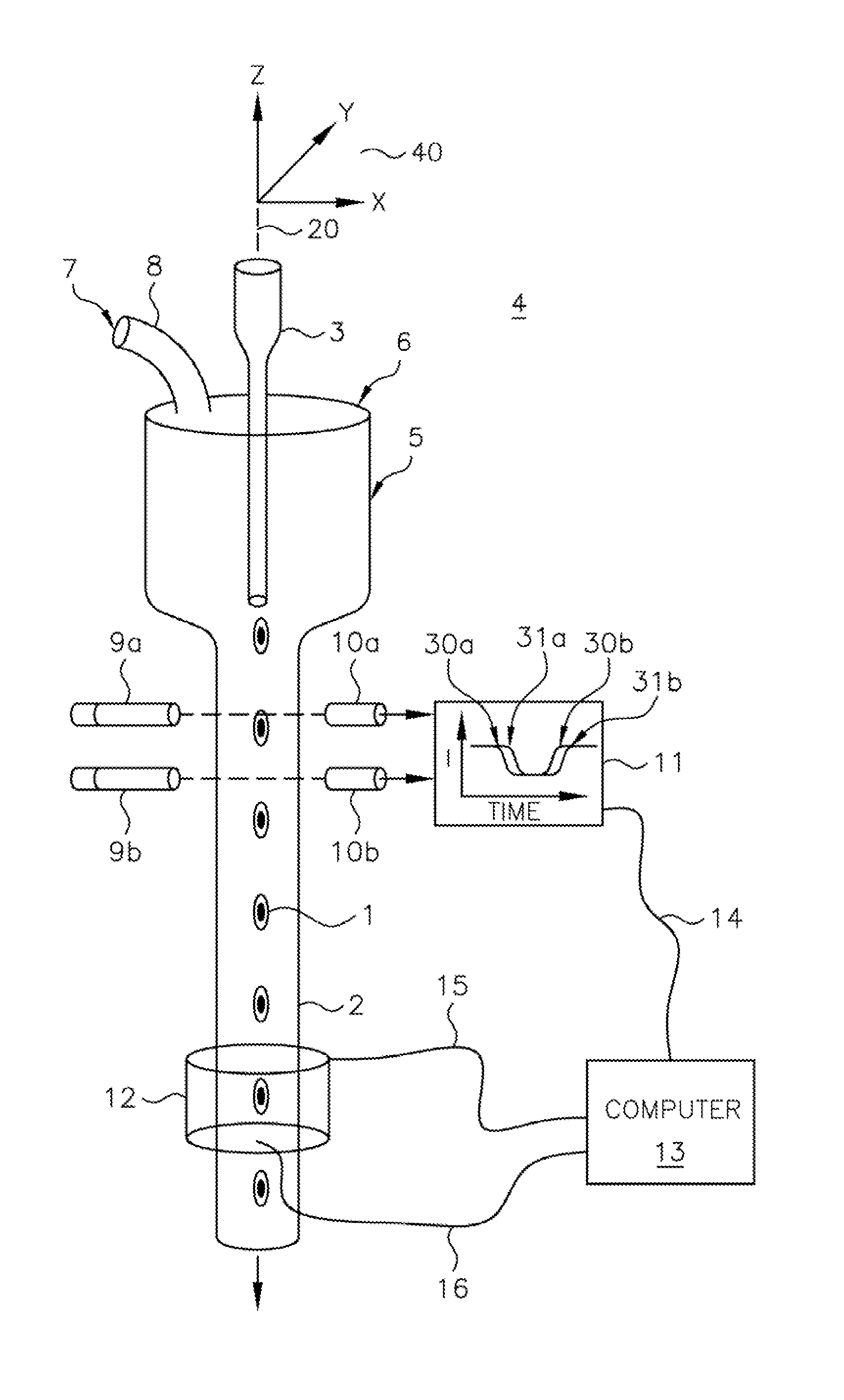
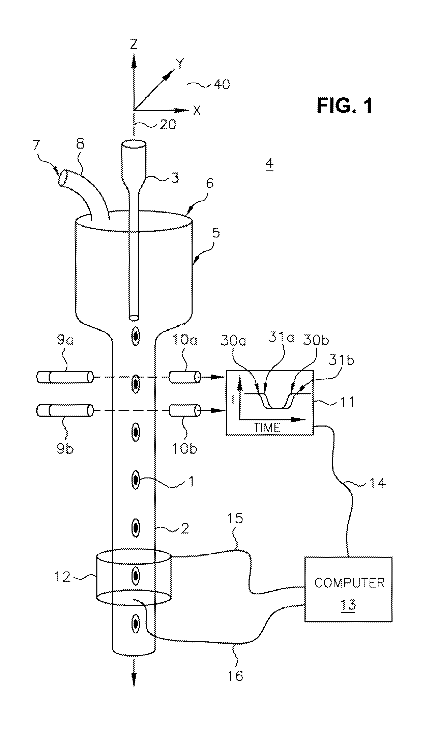
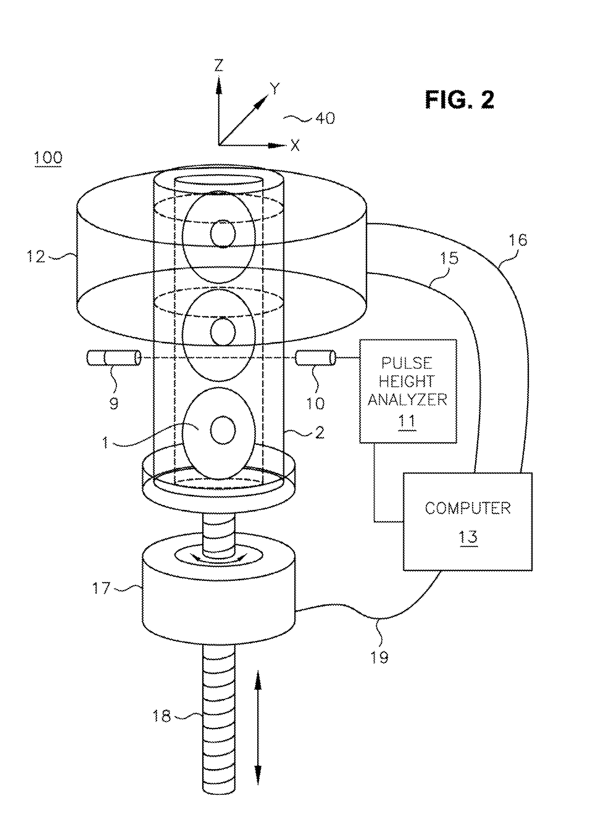
[0034]Reference will now be made in detail to the description of the invention as illustrated in the drawings. While the invention will be described in connection with these drawings, there is no intent to limit it to the embodiment or embodiments disclosed therein. On the contrary, the intent is to cover all alternatives, modifications, and equivalents included within the spirit and scope of the invention as defined by the appended claims.

[0035]The invention is further described herein with respect to specific examples relating to biological cells. It will be understood, however, that these examples are for the purpose of illustrating the principals of the invention, and that the invention is not so limited. In one example, constructing a three dimensional distribution of optical densities within a microscopic volume enables the quantification and the determination of the location of structures, molecules or molecular probes of interest. By using tagged molecular probes, the quanti...


PUM


Abstract

An optical tomography system for imaging an object of interest including a light source for illuminating the object of interest with a plurality of radiation beams. The object of interest is held within an object containing tube such that it is illuminated by the plurality of radiation beams to produce emerging radiation from the object containing tube, a detector array is located to receive the emerging radiation and produce imaging data used by a mechanism for tracking the object of interest.

Description

RELATED APPLICATION [0001]This application claims priority from and is a continuation-in-part of co-pending U.S. application Ser. No. 11 / 203,878 of Meyer et al., filed Aug. 15, 2005, entitled “OPTICAL TOMOGRAPHY OF SMALL OBJECTS USING PARALLEL RAY ILLUMINATION AND POST-SPECIMEN OPTICAL MAGNIFICATION.” that is in turn a continuation-in-part of U.S. Pat. No. 6,944,322 of Johnson and Nelson, issued Sep. 9, 2005, entitled “OPTICAL TOMOGRAPHY OF SMALL OBJECTS USING PARALLEL RAY ILLUMINATION AND POST-SPECIMEN OPTICAL MAGNIFICATION,” that is in turn a continuation-in-part of U.S. Pat. No. 6,522,775 of Alan C. Nelson, issued Feb. 18, 2003, that is in turn related to the provisional application of Alan C. Nelson, Ser. No. 60 / 279244, filed Mar. 28, 2001; both entitled “APPARATUS AND METHOD FOR IMAGING SMALL OBJECTS IN A FLOW STREAM USING OPTICAL TOMOGRAPHY.” U.S. application Ser. No. 11 / 203.878 of Meyer et al, is hereby incorporated by reference. U.S. Pat. No. 6,944,322, and U.S. Pat. No. 6,5...

Claims


Application Information

Patent Timeline
Patent Type & Authority Applications(United States)
IPC IPC(8): G06K9/00
CPCG01N15/147G01N21/4795G01N15/1475
Inventor FAUVER, MARK E.SEIBEL, ERIC J.MEYER, MICHAEL G.NELSON, ALAN C.RAHN, J. RICHARDNEUMANN, THOMASJOHNSON, ROGER H.
Owner VISIONGATE
Why Eureka
Try Eureka