Optical coherent tomography

a tomography and optical coherent technology, applied in tomography, instruments, applications, etc., can solve the problems of inability to detect high-sensitivity signal light from a specific depth, inability to observe with the micron order resolution, and limitation of the measurement depth of fiber-ring lasers, etc., to achieve high detection sensitivity to interference signals, continuous change, and high speed

Active Publication Date: 2008-07-03
SANTEC
View PDF2 Cites 47 Cited by
  • Summary
  • Abstract
  • Description
  • Claims
  • Application Information

AI Technical Summary

Benefits of technology

[0016]According to the present invention having such features, oscillation wavelength can be continuously changed with high speed by continuously changing the cavity length of the surface emission laser. Since the surface e

Problems solved by technology

The electronic endoscope is only used for observing a biological surface, and the latter diagnostic imaging system has a technical limitation to observe with the micron order resolution.
However, a signal light from a specific depth cannot be detected with high-sensitivity because reflecting lights from different depths in the interference light overlap each other in this method.
However, the fiber-ring type laser h

Method used


Image

  • Optical coherent tomography
  • Optical coherent tomography
  • Optical coherent tomography

Examples


embodiment 1

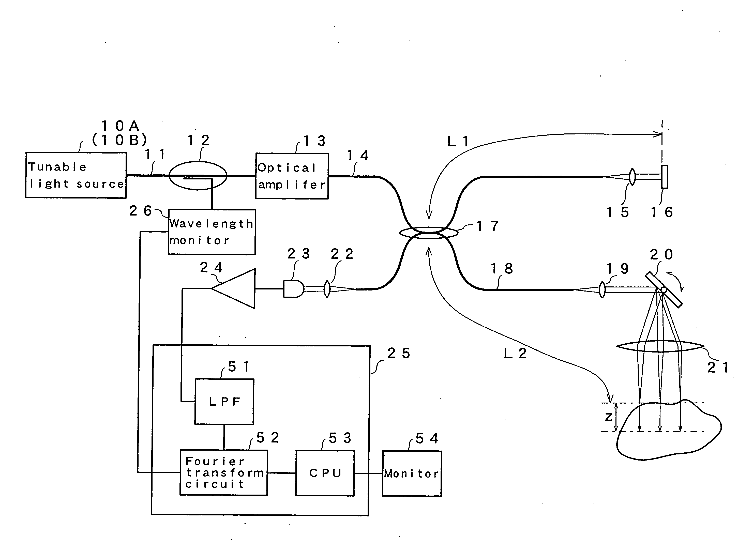
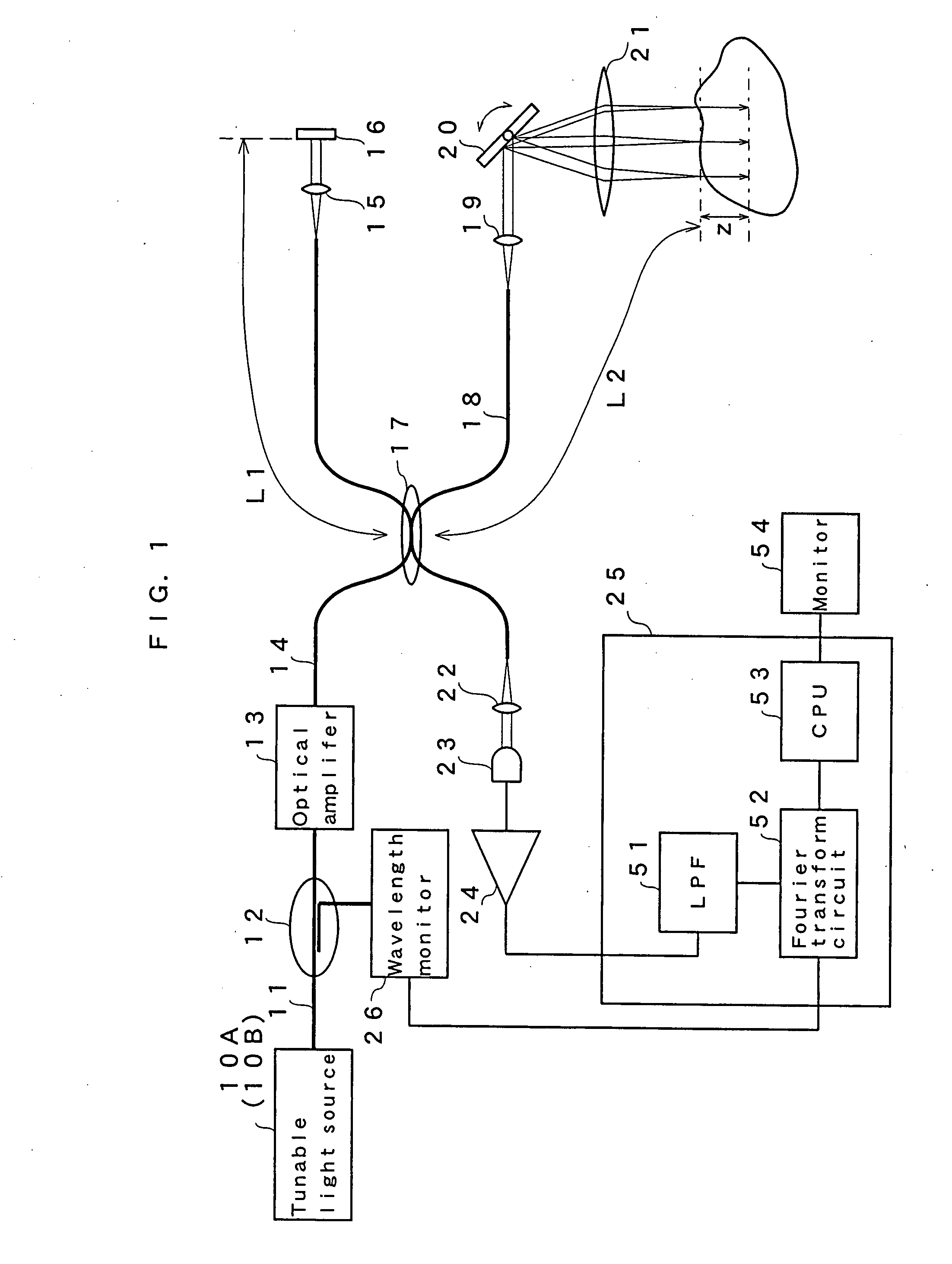
[0026]FIG. 1 is a block diagram showing an entire configuration of a tunable optical coherent tomography system of the present invention. In the figure, a tunable type surface emission laser which emits a light signal within a certain frequency range is used for a tunable light source 10A. An output of the surface emission laser is given to a division part 12 through an optical fiber 11. An optical amplifier 13 is provided to the other end of the optical fiber 11. The optical amplifier 13 amplifies laser light from the tunable light source 10A as it is, and the output is given to an optical fiber 14. A collimate lens 15 and a reference mirror 16 are provided to the other end of the optical fiber 14. In addition, a connecting part 17 for bringing other optical fiber 18 near the optical fiber 14 and for making the optical fiber 18 interfere with each other is provided in a middle portion of this optical fiber 14. A collimate lens 19 and a scanning mirror 20 for scanning light are pro...

embodiment 2

[0042]FIG. 6A is a top view showing a vertically movable mirror part of a surface emission laser in the tunable light source 10B , and FIG. 6B is an end view in A-A line thereof. FIG. 7 is an end view showing an entire configuration of the tunable light source. As shown in the figures, a surface emission laser 61 in the tunable light source is composed of an upper mirror part 62 and a bottom substrate. This surface emission laser is manufactured by bonding an independently manufactured mirror part 62 to the bottom substrate. The mirror part 62 includes a thin rectangle diaphragm 64 made of Si layer. A circular vibration part 64a of the diaphragm is supported via four hinges 65 so as to vibrate. A distribution type Bragg reflector (DBR) layer 66 having high reflectance is formed in circular form on the vibration part 64a of the diaphragm 64. The DBR layer 66 is a high reflectance layer structured in a multi-layer structure with an optical path length of λ / 4, and an AR coat layer 67 i...


PUM


Abstract

A surface emission laser light source is used as a tunable laser light source. Since the surface emission laser light source can realize a broad frequency scanning range at a high speed and in the single mode, a coherent length is longer than that of a multi mode light source. For this reason, when a tomography image is calculated by executing the Fourier transform for an output obtained from an interference optical device, measuring depth can be deepened.

Description

CROSS REFERENCE TO RELATED APPLICATION[0001]This application is a nonprovisional application of U.S. Provisional Patent Application No. 60 / 790,785 filed on Apr. 11, 2006, currently pending. The disclosure of U.S. Provisional Patent Application No. 60 / 790,785 is hereby incorporated by reference.BACKGROUND OF THE INVENTION[0002]1. Field of the Invention[0003]The present invention relates to an optical coherent tomography system, using a tunable surface emission laser source in a single mode.[0004]2. Discussion of the Related Art[0005]In association with advancement of a medical technology such as an endoscopic therapy, a diagnostic measure for noninvasively diagnosing a pathologic tissue in real time has been desired recently. For example, an electronic endoscope using a CCD, and an imaging technology using a CT, an MRI, and an ultrasonic wave are used in a diagnostic approach. The electronic endoscope is only used for observing a biological surface, and the latter diagnostic imaging ...

Claims


Application Information

Patent Timeline
IPC IPC(8): A61B6/03
CPCA61B5/0066A61B5/0073A61B5/7257H01S5/18366G01B9/02004G01B9/02091G01B9/02069G01N21/4795
Inventor CHONG, CHANGHO
Owner SANTEC
Why Eureka
Try Eureka