Multilayer structure comprising a phase change material layer and method of producing the same

a technology of phase change material and multi-layer structure, which is applied in the direction of semiconductor/solid-state device manufacturing, basic electric elements, electric devices, etc., can solve the problems of local temperature increase, flash memory scaling beyond 45 nm nodes, and the inability to meet the requirements of phase change memory production processes,

Active Publication Date: 2012-09-11
NXP BV
View PDF15 Cites 1 Cited by
  • Summary
  • Abstract
  • Description
  • Claims
  • Application Information

AI Technical Summary

Benefits of technology

[0009]It may be an object of the invention to provide a multilayer structure comprising a phase change material layer and a method of producing the same, wherein the method may provide an efficient procedure for patterning the phase change material layer of the multilayer structure.
[0014]By providing a protective insulating layer it may be possible to efficiently pattern or structure a multilayer structure comprising a phase change material layer. The protective layer may form a protection for the underlying phase change material layer so that even standard, aggressive etchants, like brome, fluorine, or chloride, may be used without deterioration of the PCM layer. Additionally, also it may be possible to avoid that nitrogen or oxygen plasmas will come in contact with the PCM. Furthermore, the protective insulating layer may also form a mask for subsequent patterning steps. Moreover, the process may be implementable or integrable into standard CMOS procedures. In particular, the structure and properties of the PCM may remain intact, which PCM layer may be part of an active region of a memory device. Using a method according to an exemplary embodiment of the invention may also avoid that the further layer, e.g. a bottom-antireflection coating layer (BARC), opening re-sputters the PCM at the side of a photo-resist used to pattern the further layer, leaving PCM residues after resist strip that are extremely difficult to remove. These PCM residues could be removed by wet strip treatment in known procedures, which however would strongly attack the PCM and / or depletes it in one or more elements leading to altered performances of the device. Since these PCM residues may be avoided when using a method according to an exemplary embodiment of the invention these wet strip treatment and the resulting drawbacks may be avoidable. Thus, it may be possible to protect the PCM from patterning chemistries in the first patterning so that standard processes may be used without affecting the PCM.
[0015]A gist of an exemplary aspect of the invention may be seen in the using of a protective layer formed on a phase change material layer which protective layer may be used to protect the PCM layer in patterning steps of layers formed on the protective layer. Thus, it may be possible to use standard patterning procedures without deteriorate the properties of the PCM layer. Residues of the protective layer and the patterning of the PCM layer may be performed by sputter dominated processes, e.g. Ar sputtering, which may not deteriorate the properties of the PCM to a great extend.
[0024]Summarizing, a gist of an exemplary aspect of the present invention may be to provide a method wherein a protective layer may be formed on a phase change material (PCM) layer which may be used to protect the PCM layer in patterning steps. This may be a new concept for patterning PCM, which may be applicable in so-called line cell PC memory. In general the method may be applicable to any devices where the patterning of PCM is needed. The protective layer may further serve as a hard mask during PCM patterning and may be used to avoid contact between standard aggressive etching chemistries and the PCM so that the properties of the PCM may remain intact. Summarizing the control of very thin PCM layer patterning may be improved, while standard CMOS processing may be usable which may enable an easy integration of the method according to an exemplary aspect of the invention into standard procedures.

Problems solved by technology

In the field of non-volatile memories, flash memory scaling beyond a 45 nm node has become a real issue.
A high current density caused by the pulse may lead to a local temperature increase.
However, the known processes for producing phase change memories may be handicapped by the fact that it is hard to pattern the phase change materials without changing the properties of the phase change material.

Method used


Image

  • Multilayer structure comprising a phase change material layer and method of producing the same
  • Multilayer structure comprising a phase change material layer and method of producing the same
  • Multilayer structure comprising a phase change material layer and method of producing the same

Examples


Embodiment Construction

[0032]The illustration in the drawing is schematically. In different drawings, similar or identical elements are provided with similar or identical reference signs.

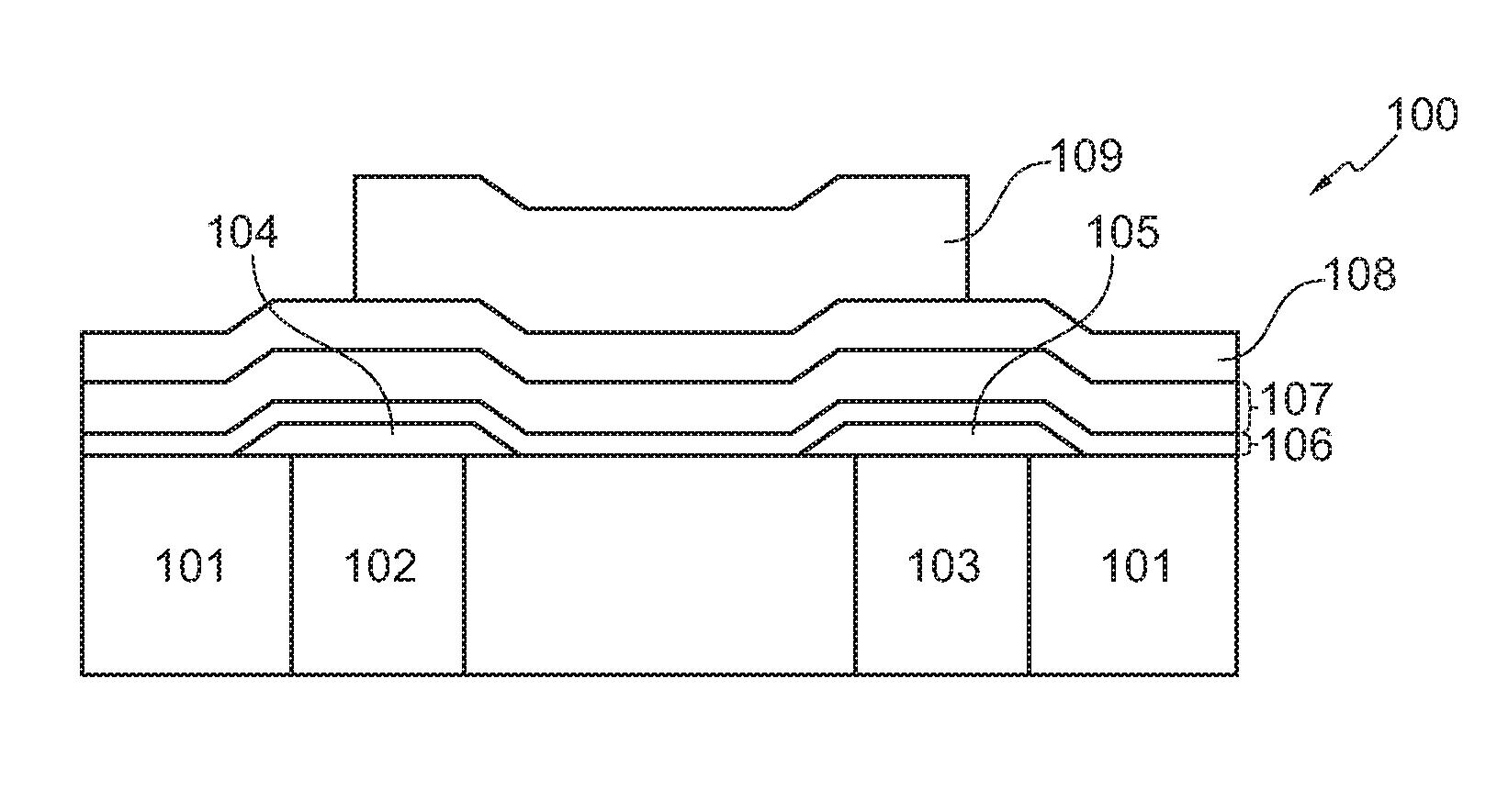
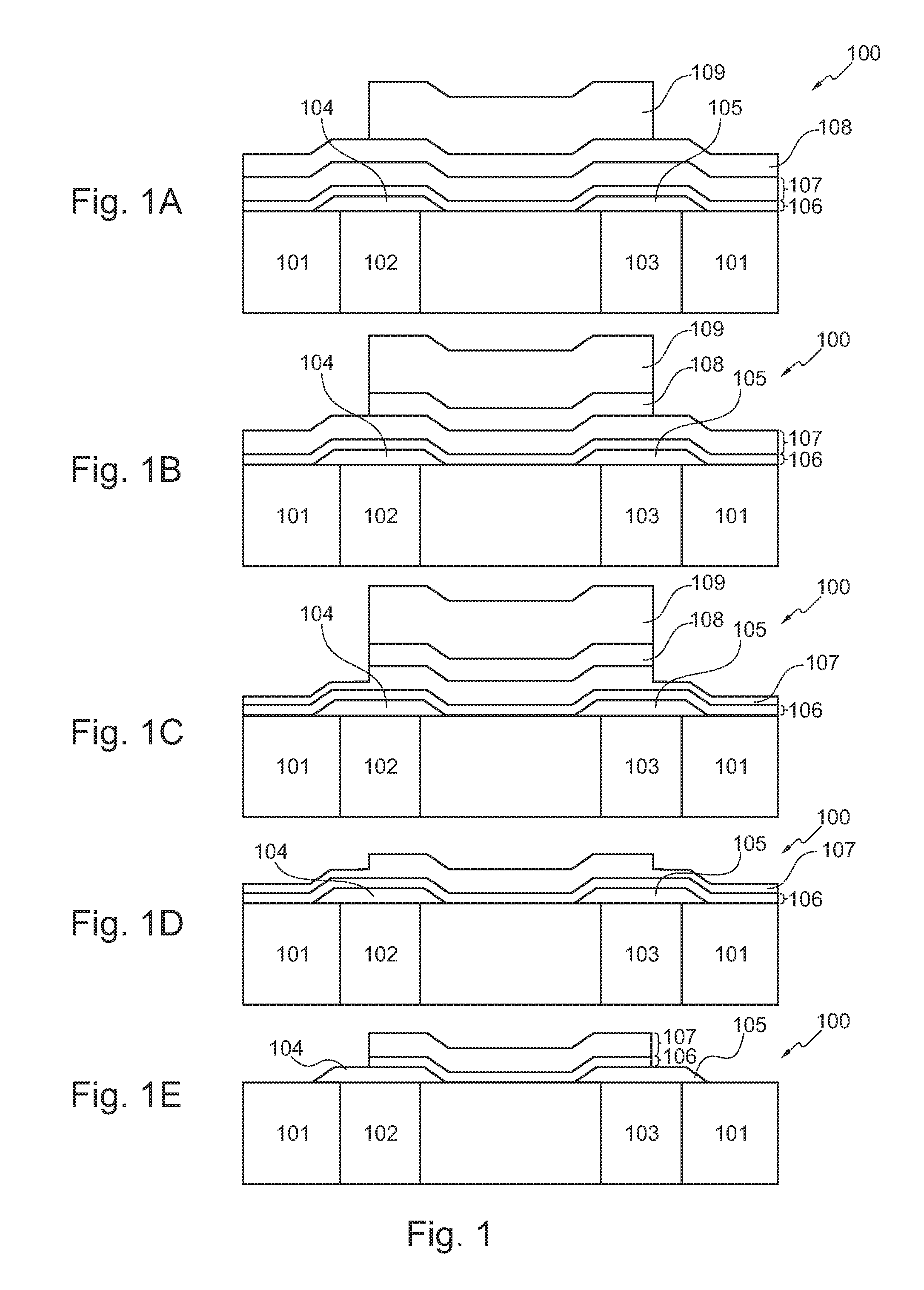
[0033]FIG. 1 shows a schematically process flow for patterning a phase change material layer according to a first exemplary embodiment of the invention. In particular, Fig. 1A shows a multilayer structure 100 which may be a part of a memory cell, wherein the multilayer structure 100 comprises a base layer 101 and two conductor paths 102 and 103 burrowed in the substrate 101 or formed by a damascene process. The conductor paths may be formed of metal, e.g. copper. The conductor paths 102 and 103 are connected to electrodes 104 and 105, respectively, which may be formed by tantalum-nitride (TaN) for example. On the substrate 101 and the electrodes 104 and 105 a phase change material (PCM) layer 106 is formed e.g. by using GeTe-Sb2Te3 such as Ge2Sb2Te5. Onto the PCM layer 106 a protective layer 107, e.g. a protective insulat...


PUM

PropertyMeasurementUnit
thicknessaaaaaaaaaa
phase changeaaaaaaaaaa
phaseaaaaaaaaaa

Abstract

A method of producing a multilayer structure is provided, wherein the method comprises forming a phase change material layer onto a substrate, forming a protective layer, forming a further layer on the protective layer, patterning the further layer in an first patterning step, patterning the protective layer and the phase change material layer by a second patterning step. In particular, the first patterning step may be an etching step using chemical etchants. Moreover, electrodes may be formed on the substrate before the phase change material layer is formed, e.g. the electrodes may be formed on one level, e.g. may form a planar structure and may not form a vertically structure.

Description

FIELD OF THE INVENTION[0001]The invention relates to a multilayer structure comprising a phase change material layer, in particular to a memory cell comprising a phase change material layer.[0002]The invention further relates to a method of producing a multilayer structure comprising a phase change material layer.BACKGROUND OF THE INVENTION[0003]In the field of non-volatile memories, flash memory scaling beyond a 45 nm node has become a real issue. Technologies to face this challenge are ferroelectric, magnetic and phase change memories, the latter one being promising for the replacement of flash and showing characteristics that may allow replacement of other types of memories such as DRAM. Phase change memories are a possible solution for the unified memory being an important step in the electronics art. OTP (“on time programmable”) and MTP (“multiple times programmable”) memories open a field that may present a great opportunity for phase change memories as well.[0004]Phase change...

Claims


Application Information

Patent Timeline
Patent Type & Authority Patents(United States)
IPC IPC(8): H01L21/20
CPCH01L45/06H01L45/1226H01L45/144H01L45/1675H10N70/231H10N70/823H10N70/8828H10N70/063
Inventor DELHOUGNE, ROMAINLISONI, JUDITPARASCHIV, VASILE
Owner NXP BV
Why Eureka
Try Eureka