Mechanical flow battery

a flow battery and flow tube technology, applied in the direction of machines/engines, positive displacement liquid engines, pumping pumps, etc., can solve the problem of limiting the placement of the flywheel system on the moving platform

Inactive Publication Date: 2012-09-18
HSU YEN WEI +1
View PDF9 Cites 11 Cited by
  • Summary
  • Abstract
  • Description
  • Claims
  • Application Information

AI Technical Summary

Problems solved by technology

The high-speed rotor is sensitive to any outside angular momentum, which limits the flywheel system to be placed on a moving platform.

Method used


Image

  • Mechanical flow battery
  • Mechanical flow battery
  • Mechanical flow battery

Examples


Embodiment Construction

[0020]The present invention “a mechanical flow battery” can be fixed on a moving platform as a power generator and battery. The mechanical flow battery comprises a flywheel system in which a high-speed rotating rotor is sensitive to angular momentum so that it has to be isolated from any outside gyroscopic torque. The invention has employed the structure of gyroscope to solve the problems.

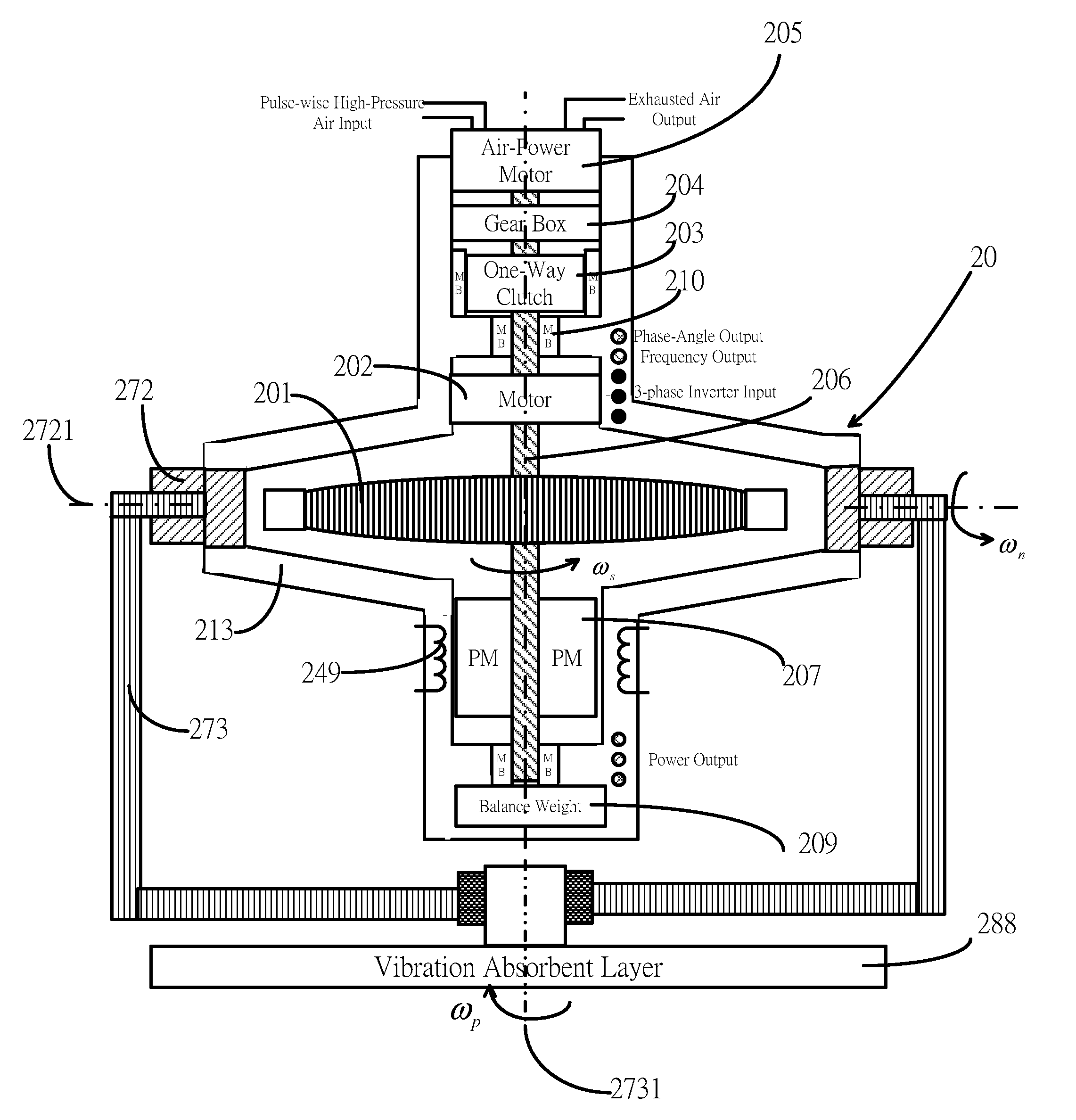
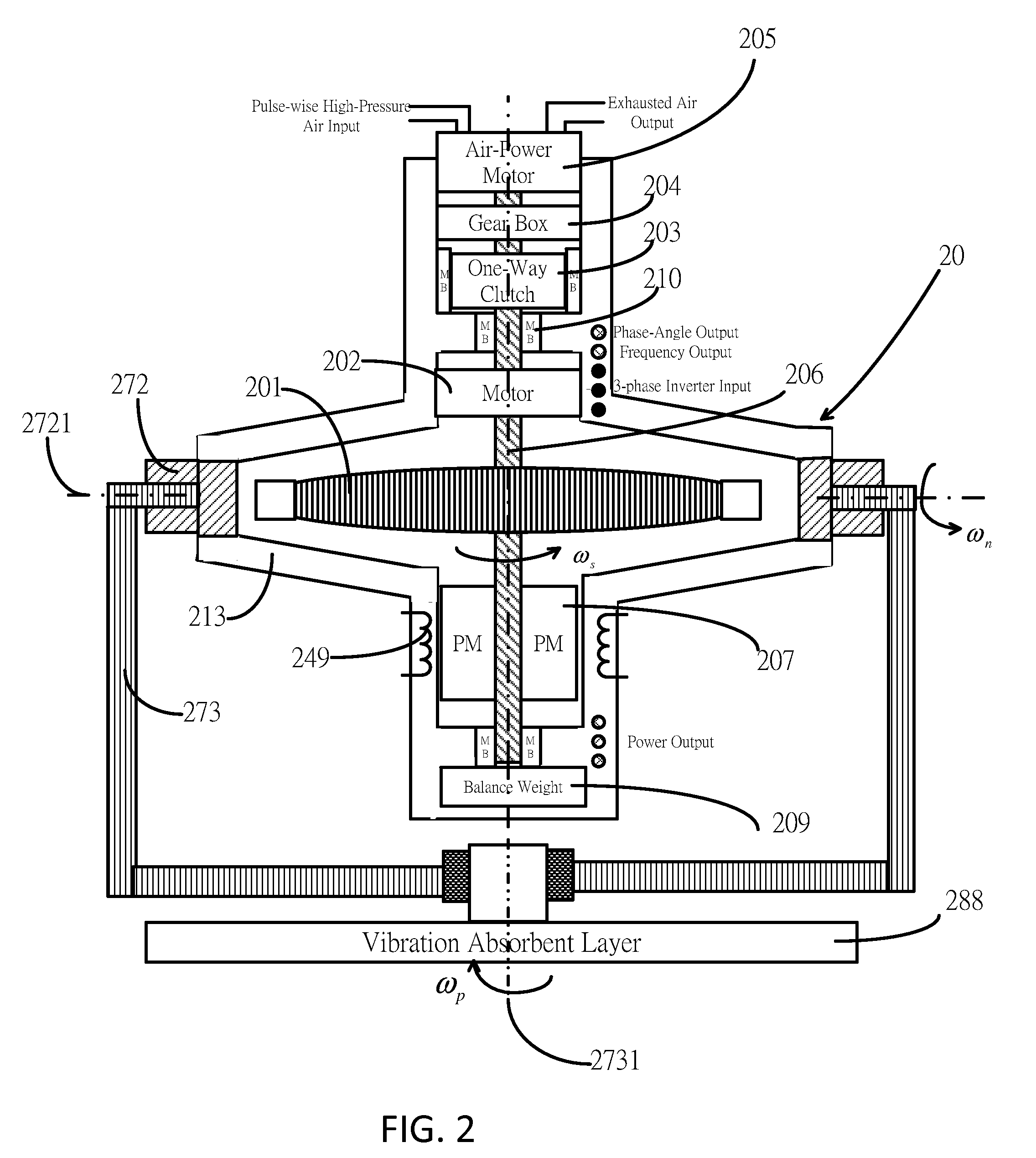
[0021]FIG. 2 has shown the present invention “a mechanical flow battery” or simply “flow battery” in cross view. The mechanical flow battery comprises a flywheel system 20, a nutation frame 272 and a precession frame 273 which is mounted on a vibration absorbent layer 288 to be isolated from any outside vibrations.

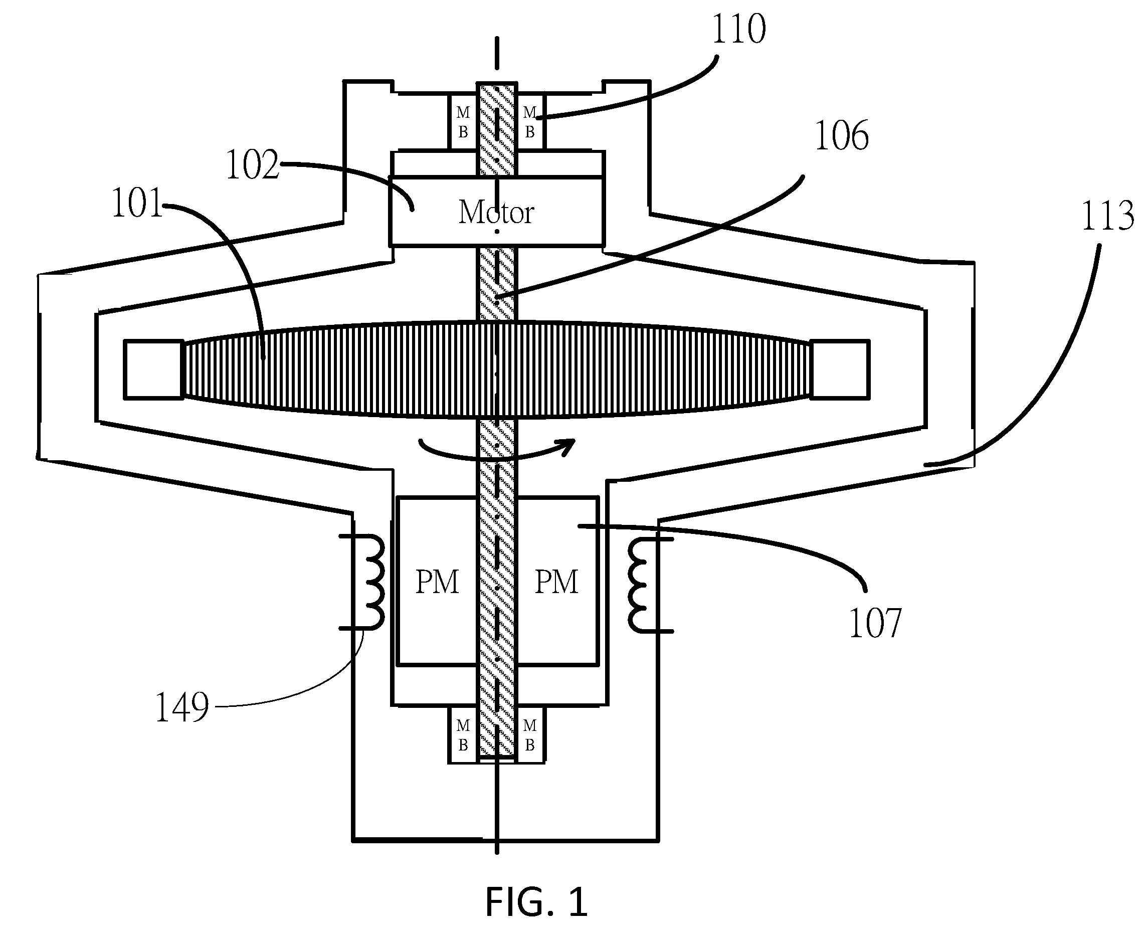
[0022]The flywheel system 20 of the mechanical flow battery comprises a rotor 201, a spinning axis 206, at least a permanent magnet shown by a number 207, a motor 202, a housing 213, at least a conductive coil shown by a number 249, a plurality of bearings shown by a number 210, an air-po...


PUM


Abstract

A mechanical flow battery comprises a flywheel system in which a spinning axis can be driven by an air-powered motor and the structure of the gyroscope is employed in the mechanical flow battery. The structure of the gyroscope can be constructed by coupling the housing of the flywheel system with a nutation frame which couples a precession frame so that the spinning axis in the flywheel can be isolated from any outside gyroscopic torque.

Description

CROSS-REFERENCE TO RELATED APPLICATIONS[0001]Not ApplicableSTATEMENT REGARDING FEDERALLY SPONSORED RESEARCH OR DEVELOPMENT[0002]Not ApplicableTHE NAMES OF PARTIES TO A JOINT RESEARCH AGREEMENT OK TO ENTER[0003]Not ApplicableBACKGROUND OF THE INVENTION[0004]1. Field of the Invention[0005]The present invention relates to an electrical generator and battery, and, more particularly, a mechanical flow battery. The mechanical flow battery comprises a flywheel and has the structure of gyroscope so that the spinning axis inside the flywheel system can be isolated from any outside gyroscopic forces. The present invention also relates to a variable-volume-controlled container as an air source to drive the spinning axis inside mechanical flow battery.[0006]2. Description of Related Art[0007]Flywheel system has been known to us for many years. Flywheel system works by accelerating a rotor inside the flywheel to a very high speed and maintaining the energy in the system as rotational energy. The...

Claims


Application Information

Patent Timeline
Patent Type & Authority Patents(United States)
IPC IPC(8): H02K7/02
CPCH02K7/025Y02E60/16
Inventor WU, WHEI CHYOUHSU, YEN-WEI
Owner HSU YEN WEI
Why Eureka
Try Eureka