System and method for seamless task-directed autonomy for robots

a robot and task-directed technology, applied in the field of robotics, can solve the problems of not being able to unable to sustainly provide a kernel of basic robot competence and decision, and the behavior functionality created for one robot may not be easily ported to new robots

Active Publication Date: 2012-09-18
BATTELLE ENERGY ALLIANCE LLC +1
View PDF144 Cites 67 Cited by
  • Summary
  • Abstract
  • Description
  • Claims
  • Application Information

AI Technical Summary

Benefits of technology

[0010]Embodiments of the present invention comprise methods and systems that provide a more intuitive approach for the user to direct a robot's activities without having to understand the available robot behaviors or autonomy levels. This intuitive approach provides a bridge between a user's intentions and a robot's behaviors by creating a new user interface and adjustments to robot initiative and behavior that does not need to be directly controlled by the user.

Problems solved by technology

There has been no sustained attempt to provide a kernel of basic robot competence and decision making that can be used to bootstrap development across many different applications.
Some architectures have been proposed that provide a generic application programming interface (API) for querying various sensors and commanding various actuators; however, many of these architectures have been limited to raw inputs and outputs rather than provide the intelligence and behavior to a robot.
As a result, the behavior functionality created for one robot may not be easily ported to new robots.
Other architectures have been proposed to allow limited behaviors to port across different robot platforms, but these have generally been limited to specific low-level control systems.
The problem with robots today is that they are not very bright.
The reality is that today's robots generally lack the ability to make any decisions on their own and rely on continuous guidance by human operators watching live video from on-board cameras.
Furthermore, the intense concentration needed for controlling the robot can detract from achieving mission goals.

Method used


Image

  • System and method for seamless task-directed autonomy for robots
  • System and method for seamless task-directed autonomy for robots
  • System and method for seamless task-directed autonomy for robots

Examples


Embodiment Construction

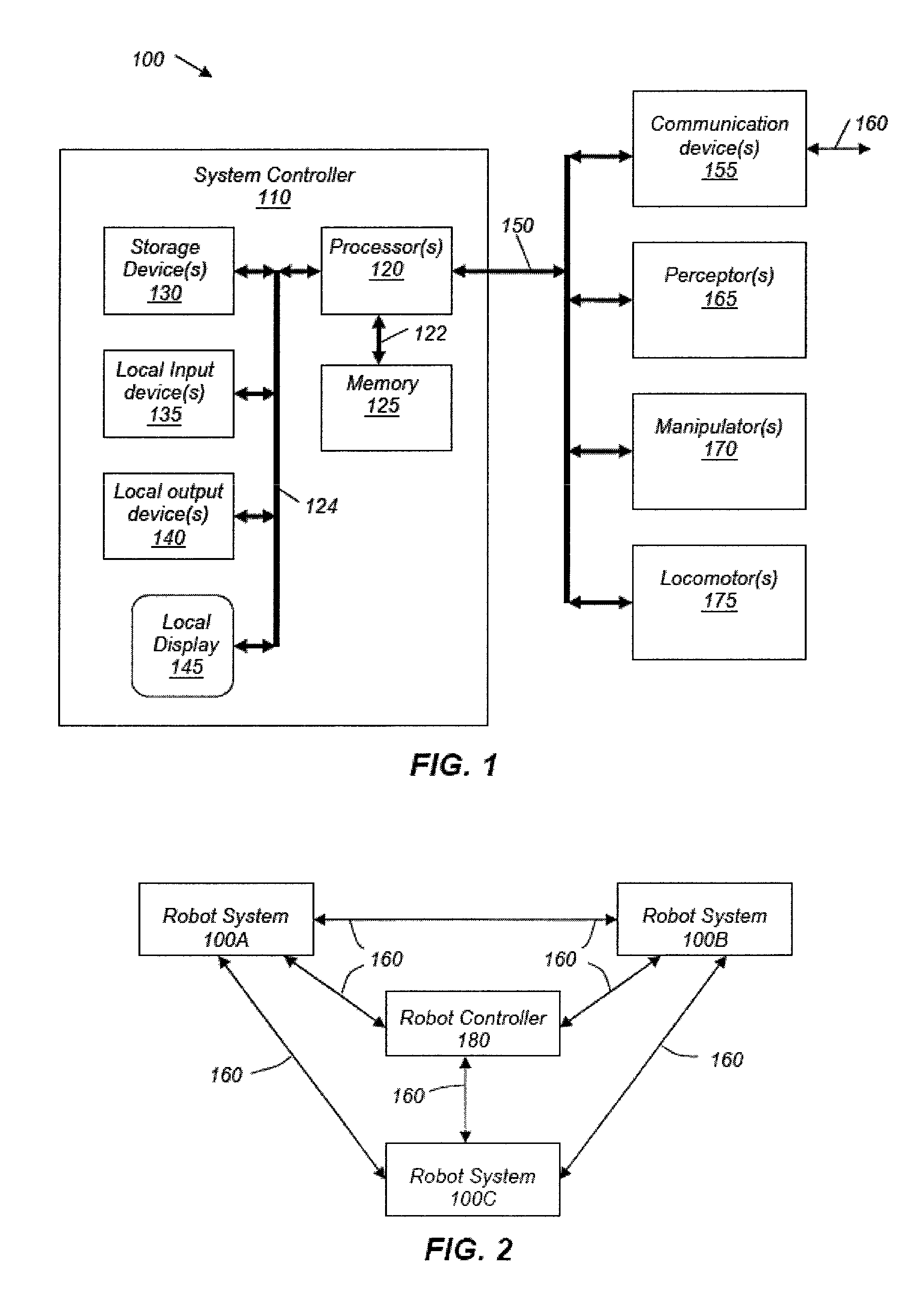
[0052]In the following description, circuits and functions may be shown in block diagram form in order not to obscure the present invention in unnecessary detail. Conversely, specific circuit implementations shown and described are exemplary only and should not be construed as the only way to implement the present invention unless specified otherwise herein. Additionally, block definitions and partitioning of logic between various blocks is exemplary of a specific implementation. It will be readily apparent to one of ordinary skill in the art that the present invention may be practiced by numerous other partitioning solutions. For the most part, details concerning timing considerations and the like have been omitted where such details are not necessary to obtain a complete understanding of the present invention and are within the abilities of persons of ordinary skill in the relevant art.

[0053]In this description, some drawings may illustrate signals as a single signal for clarity o...


PUM


Abstract

Systems, methods, and user interfaces are used for controlling a robot. An environment map and a robot designator are presented to a user. The user may place, move, and modify task designators on the environment map. The task designators indicate a position in the environment map and indicate a task for the robot to achieve. A control intermediary links task designators with robot instructions issued to the robot. The control intermediary analyzes a relative position between the task designators and the robot. The control intermediary uses the analysis to determine a task-oriented autonomy level for the robot and communicates target achievement information to the robot. The target achievement information may include instructions for directly guiding the robot if the task-oriented autonomy level indicates low robot initiative and may include instructions for directing the robot to determine a robot plan for achieving the task if the task-oriented autonomy level indicates high robot initiative.

Description

CONTRACTUAL ORIGIN OF THE INVENTION[0001]This invention was made with government support under Contract No. DE-AC07-05-ID14517 awarded by the U.S. Department of Energy. The government has certain rights in the invention.CROSS-REFERENCE TO RELATED APPLICATIONS[0002]The present application is related to: U.S. patent application Ser. No. 11 / 428,769, filed Jul. 5, 2006, now U.S. Pat. No. 7,668,621, issued Feb. 23, 2010; U.S. patent application Ser. No. 11 / 428,757, filed Jul. 5, 2006, now U.S. Pat. No. 8,073,564, issued Dec. 6, 2011; U.S. patent application Ser. No. 11 / 428,729, filed Jul. 5, 2006, now U.S. Pat. No. 7,801,644, issued Sep. 21, 2010; U.S. patent application Ser. No. 11 / 428,650, filed Jul. 5, 2006, now U.S. Pat. No. 7,620,477, issued Nov. 17, 2009; U.S. patent application Ser. No. 11 / 428,646, filed Jul. 5, 2006, now U.S. Pat. No. 7,584,020, issued Sep. 1, 2009; U.S. patent application Ser. No. 11 / 428,637, filed Jul. 5, 2006, now U.S. Pat. No. 7,587,260, issued Sep. 8, 2009; ...

Claims


Application Information

Patent Timeline
Patent Type & Authority Patents(United States)
IPC IPC(8): G06F17/00G05B15/00
CPCB25J9/161B25J9/162B25J9/1666G05D1/0044G05D1/0088G05B2219/33051G05B2219/35472G05B2219/40442G05D1/024G05D1/0274G05D1/0278G05D2201/0209G05B2219/39212
Inventor NIELSEN, CURTISBRUEMMER, DAVIDFEW, DOUGLASWALTON, MILES
Owner BATTELLE ENERGY ALLIANCE LLC
Why Eureka
Try Eureka