Control valve system with cycle monitoring, diagnostics and degradation prediction

a control valve and cycle monitoring technology, applied in the field of fluid control valve performance monitoring, can solve problems such as damage to equipment, scrap produced by manufacturing equipment, etc., and achieve the effect of avoiding production interruptions or losses

Active Publication Date: 2012-09-18
ROSS OPERATING VALVE CO
View PDF20 Cites 39 Cited by
  • Summary
  • Abstract
  • Description
  • Claims
  • Application Information

AI Technical Summary

Problems solved by technology

This can result in scrap being produced by the manufacturing equipment, damage to the equipment, and production downtime.
Production downtime reduces efficiency in the manufacturing process and has direct bottom line costs associated with it.
A valve fault (i.e., a condition outside of the valve's normal performance specifications) can result from problems with any number of internal operational components.
Components may experience wear or the components may suffer from contamination that becomes introduced during the valve's service life.
Eventually, the performance of the valve may degrade to such a degree that it is no longer capable of fulfilling its intended task.
However, prior to that point, the valve typically displays diminished performance.
This diminished performance often goes unnoticed during the ongoing manufacturing operations because the valve otherwise continues to operate within acceptable limits and the manufacturing output does not initially suffer.
Most conventional valve monitoring systems, however, are incapable of addressing the issue of gradually diminished performance nor can they accurately track degradation in a manner to provide any form of prediction of expected remaining serviceable life.
Due to the foregoing limitations of the prior art, impending faults have not been accurately predicted.

Method used


Image

  • Control valve system with cycle monitoring, diagnostics and degradation prediction
  • Control valve system with cycle monitoring, diagnostics and degradation prediction
  • Control valve system with cycle monitoring, diagnostics and degradation prediction

Examples


Embodiment Construction

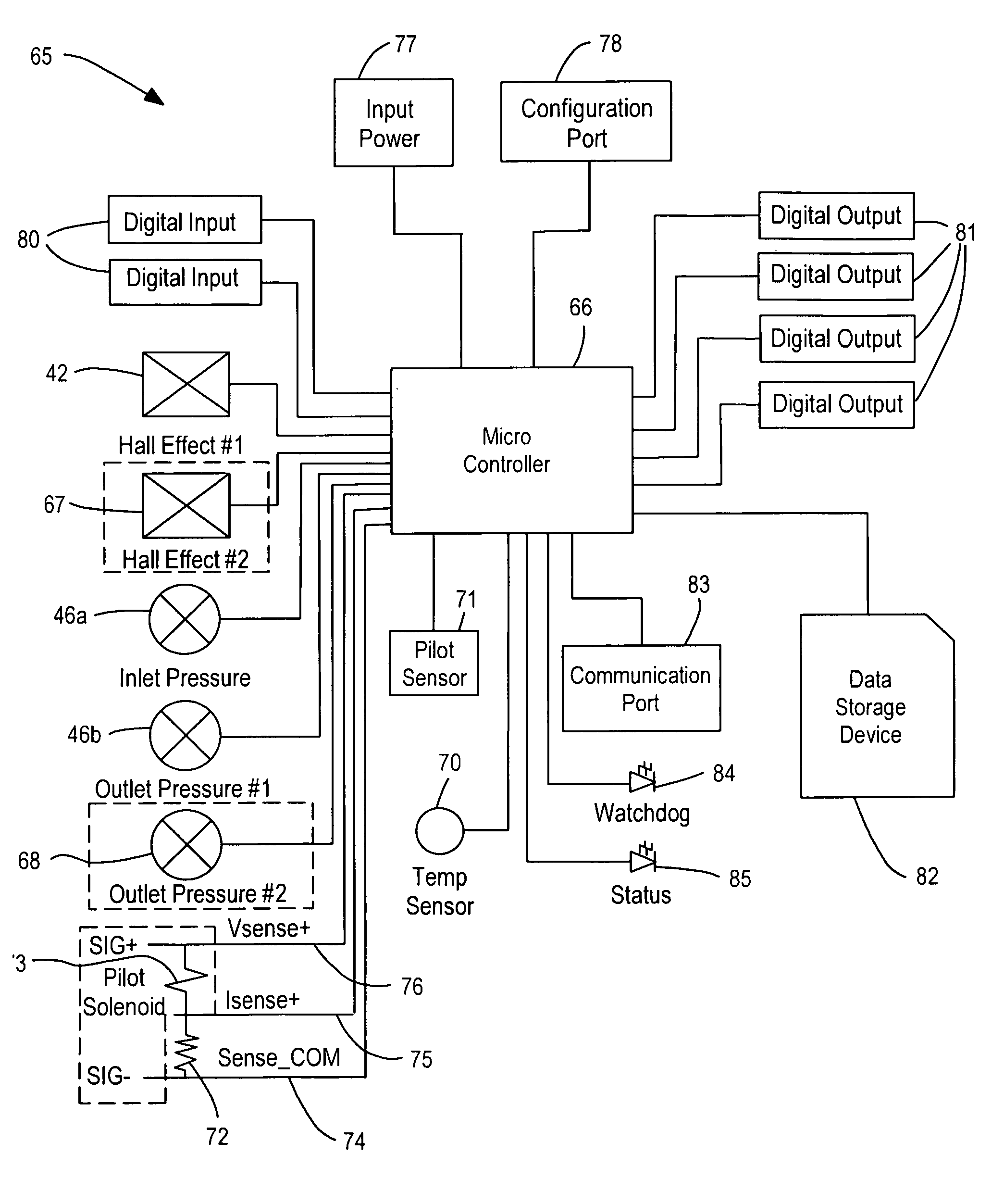
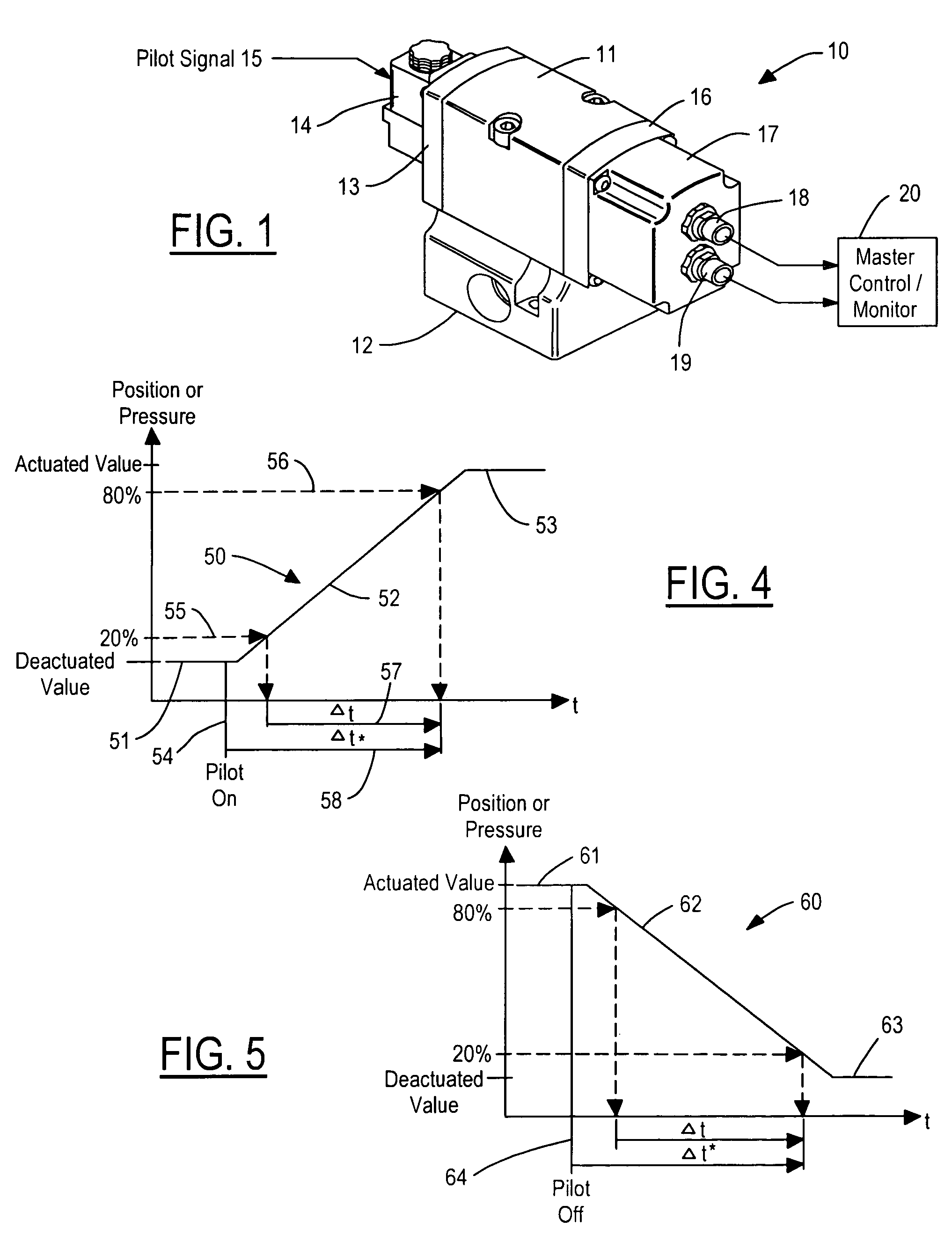
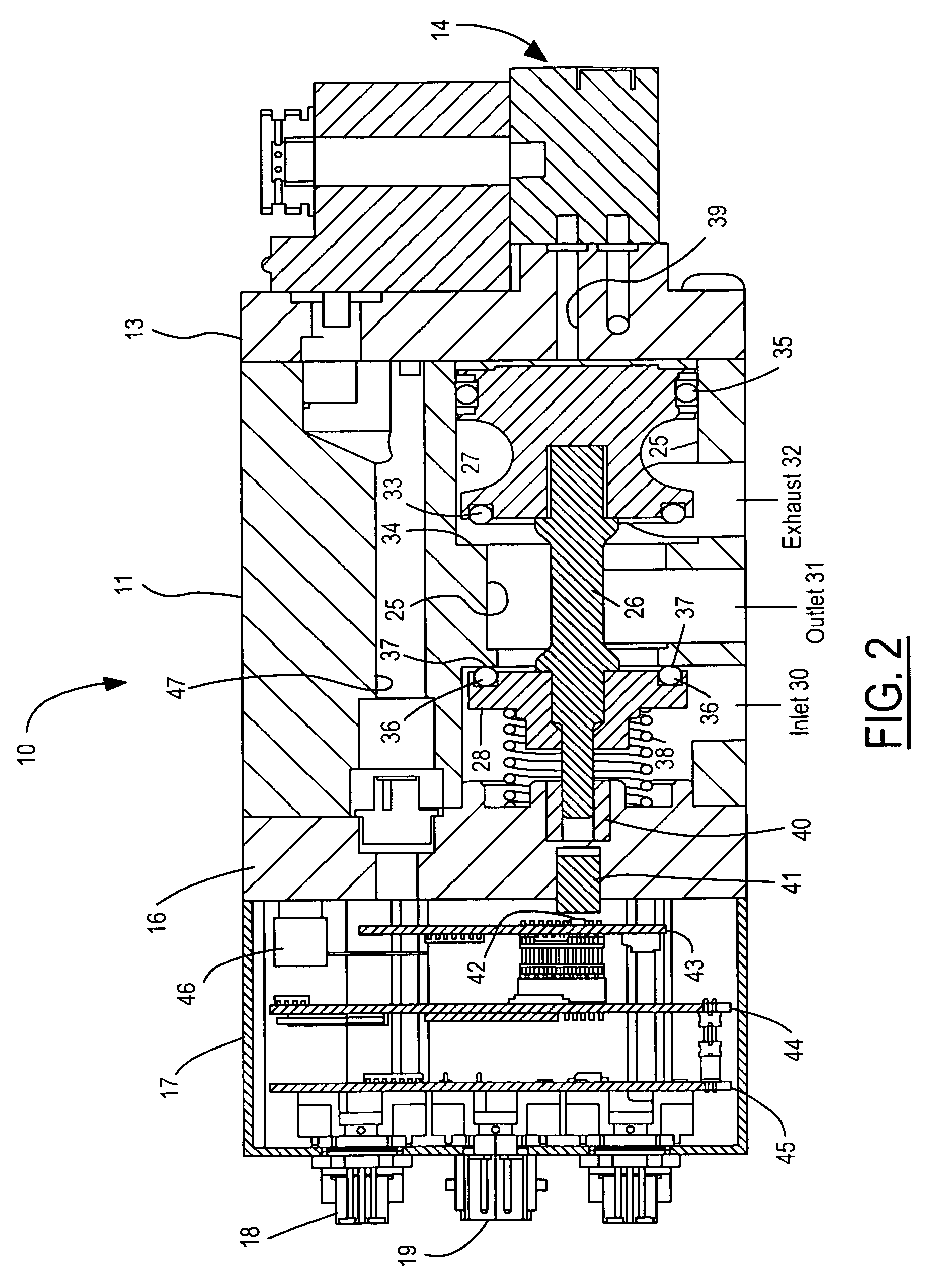
[0019]Referring now to FIG. 1, a valve system 10 includes a valve body 11 mounted to a base 12. Valve body 11 includes conventional valve internal parts for supplying fluid between various ports in base 12. A cover plate 13 mounts a pilot valve 14 to valve body 11. A pilot command signal 15 coupled to pilot valve 14 may be an electrical signal when the pilot valve 14 is an electrical solenoid-operated valve or may be a pneumatic signal when pilot valve 14 is pneumatically controlled. An end cap 16 is provided for mounting a housing 17 to valve body 11. Housing 17 includes the monitoring electronics of the present invention in the form of a logic unit and has end connectors 18 and 19 for electrically connecting the electronics to a master control / monitor 20.

[0020]Valve body 11, base 12, and pilot valve 14 may be any type of conventional fluid control valves employing one or more moving valve elements. Single valves, double valves, two-position valves, three-position valves, or any ot...


PUM


Abstract

A valve body has an elongated bore in communication with an inlet port and an outlet port. A valve element is movable within the bore between deactuated and actuated positions. A valve sensor generates a sensor signal indicative of an instantaneous parameter of the valve that changes between the deactuated and actuated positions. A logic unit receives the sensor signal and a pilot command signal that actuates the valve. A predetermined change in the pilot command signal causes the logic unit to determine a cycle parameter responsive to a time period between two predetermined events. At least the beginning or end of the time period corresponds to a predetermined value of the sensor signal. The individual determinations of the cycle parameter are accumulated to obtain an expected cycle parameter. The logic unit generates an indication signal when the cycle parameter exhibits a predetermined variance from the expected cycle parameter.

Description

CROSS REFERENCE TO RELATED APPLICATIONS[0001]Not Applicable.STATEMENT REGARDING FEDERALLY SPONSORED RESEARCH[0002]Not Applicable.BACKGROUND OF THE INVENTION[0003]The present invention relates in general to fluid control valves, and, more specifically, to performance monitoring of fluid control valves.[0004]Fluid control valves, such as pneumatic valves, perform many industrial functions that involve moving fluid energy from an inlet to one or more outlets and from the one or more outlets to one or more exhaust ports. The fluid energy may be used to control motion of pneumatic cylinders, for example. A valve that performs outside of its normal performance specifications can prevent the system within which it is installed from achieving its required function. This can result in scrap being produced by the manufacturing equipment, damage to the equipment, and production downtime. Production downtime reduces efficiency in the manufacturing process and has direct bottom line costs associ...

Claims


Application Information

Patent Timeline
Patent Type & Authority Patents(United States)
IPC IPC(8): G05D7/00
CPCF15B19/005F16K37/0041G05B23/0283G05B23/0235Y10T137/8242Y10T137/1116
Inventor CUMMINGS, ERIC O.FRAZIER, RICHARD J.DIVELBISS, DONALD S.DIVELBISS, TERRY L.HASELDEN, JR., DAVID W.
Owner ROSS OPERATING VALVE CO
Why Eureka
Try Eureka