Conveyor for transporting and overturning flat objects, such as sheaves of paper or printed materials

a technology for overturning and flat objects, which is applied in the direction of conveyor parts, thin material processing, function indicators, etc., can solve the problems of increasing the risk of jamming, the order may be unavoidable in such cases, and the construction and operation complexity of a device such as the one described above is self-evident, so as to achieve the effect of linking conveyors and being constructionally and functionally simpler

Active Publication Date: 2012-09-25
CMC SRL
View PDF17 Cites 3 Cited by
  • Summary
  • Abstract
  • Description
  • Claims
  • Application Information

AI Technical Summary

Benefits of technology

[0016]The aim of the present invention is to modify the conveyor linking to the envelope-filling station, primarily in order to make the linking conveyor both constructionally and functionally simpler.
[0017]Structural simplification of the conveyor must improve and speed up operation of the conveyor, eliminating halts and downtimes.
[0018]In the above-mentioned ambit of simplification, a further aim of the invention is to improve the structure of the conveyor in such a way as to make the handling of sheaves of different thicknesses easier, while eliminating mobile support elements for the rollers.
[0019]A still further aim of this invention, in accordance with the aims mentioned above, is to have a positive impact on machine construction costs, reducing the need for maintenance and adjustment of operating organs as far as possible.

Problems solved by technology

This may be caused by a particular order of deposition of the sheets along the preparation line, which order may in such cases be unavoidable.
The constructional and operational complexity of a device such as the one described above is self-evident.
Equally evident are the drawbacks associated with this type of conveyor, where transfer to the overturning device increases the risk of jamming, in addition evidently to slowing down operations.
A problem with these known conveyor devices is constituted by the sheaf input and output sections of the linking conveyor.
Although simple, this solution nevertheless impacts negatively on construction costs, in addition to requiring greater maintenance on organs which need to be able to move constantly without hindrance so as to enable the sheaves to pass with ease.

Method used


Image

  • Conveyor for transporting and overturning flat objects, such as sheaves of paper or printed materials
  • Conveyor for transporting and overturning flat objects, such as sheaves of paper or printed materials
  • Conveyor for transporting and overturning flat objects, such as sheaves of paper or printed materials

Examples


Embodiment Construction

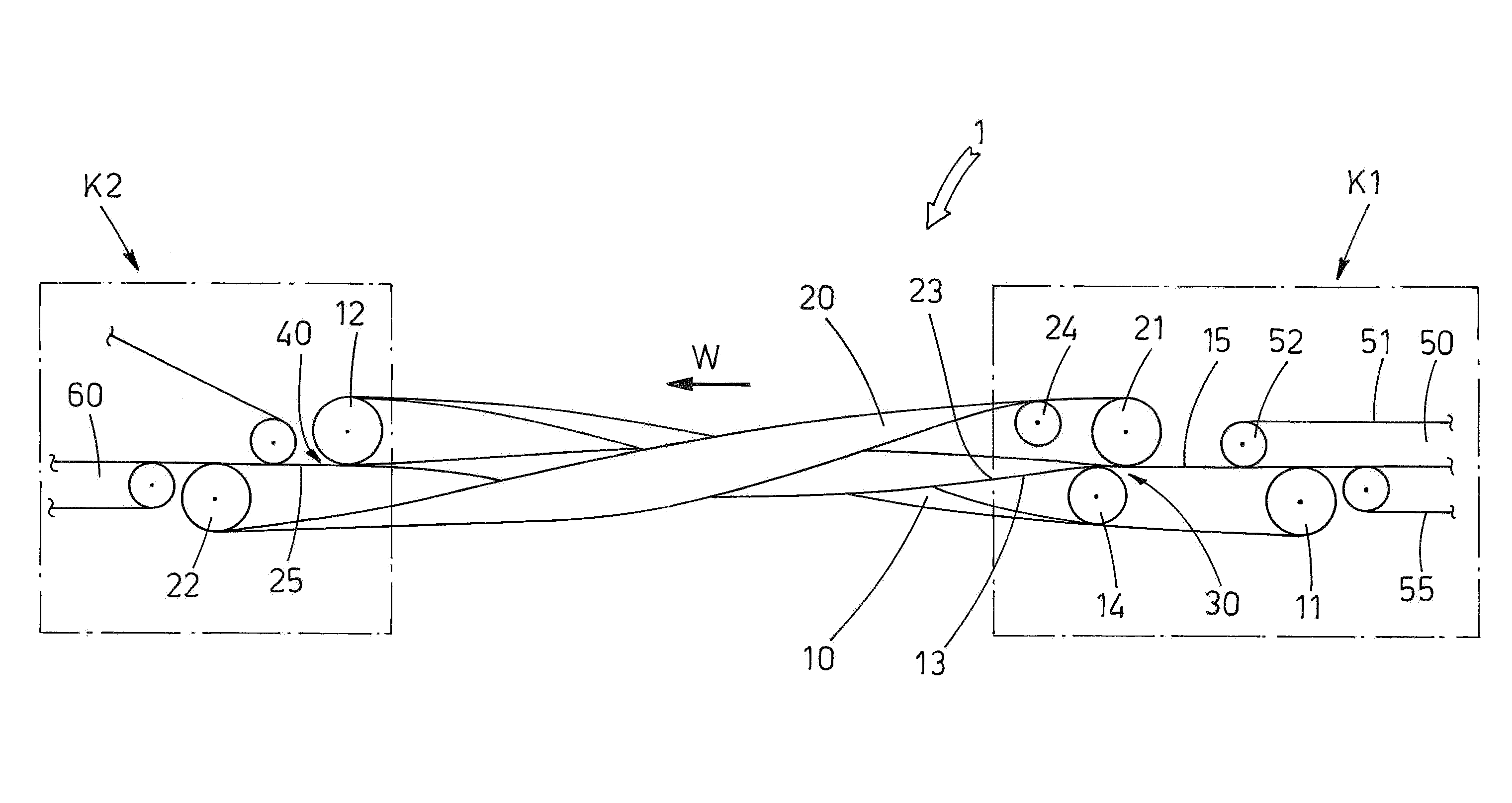
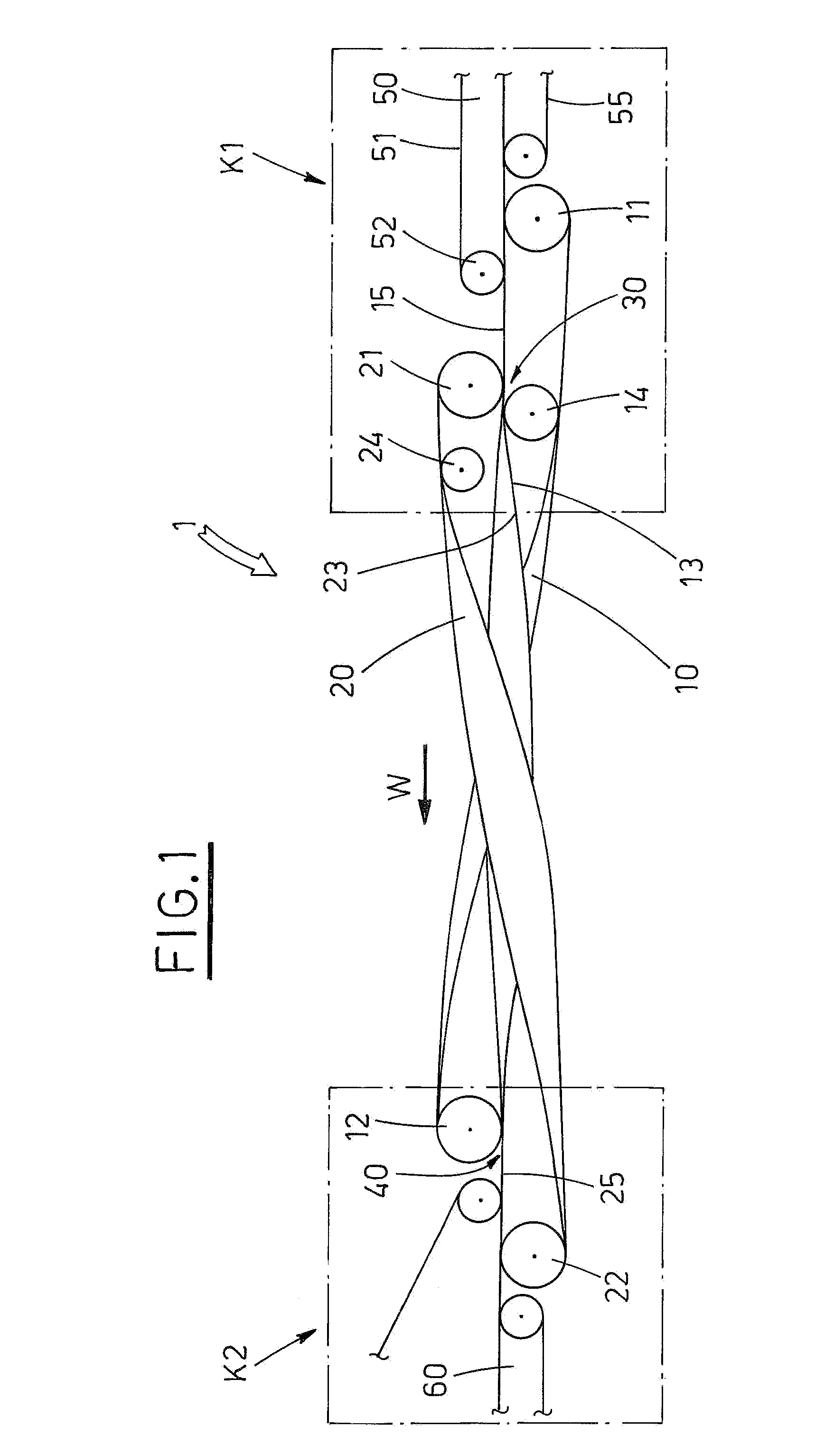
[0028]In the above figures, reference number 1 indicates the conveyor device which is the object of this invention, and which constitutes the link between the preparation line 50 (of which only the end part is shown in FIG. 1) of the sheaves 2 of sheets of paper or printed material (shown by way of example using dotted lines in FIG. 4 and for the sake of simplicity referred-to as “sheaves” hereinafter), and the envelope-filling station, of which only the access section 60 is shown.

[0029]The conveyor of the invention, in addition to its linking function as described above, also has the task of overturning the sheaves 2. The conveyor 1 is constituted by two belts, 10, 20 each having an active branch facing the active branch of the other belt and counterposed to it, as will be better described herein below.

[0030]A first belt 10 is ring-wound and fitted on parallel rollers, respectively an upstream roller 11 and a downstream roller 12. The rollers 11, 12 are rotatingly fitted on respect...


PUM

PropertyMeasurementUnit
widthaaaaaaaaaa
elastic tractionaaaaaaaaaa
elastic forceaaaaaaaaaa

Abstract

In a conveyor for transporting and overturning flat objects, such as sheaves of paper or printed materials, a first ring-bound belt (10) is positioned above a second belt (20), which is also ring-wound, in such a way that an active branch (13) of the first belt (10) faces and is in contact with a corresponding active branch (23) of the second belt (20). The first belt (10) and the second belt (20) are subject to an axial torsion of 180°, thus exchanging their positions in such a way that the sheaves (2) which are inserted into an input section (30) exit overturned from an output section (40). Further, the first belt (10) is longitudinally staggered in relation to the second belt (20), in such a way that an upstream roller (11) of the first belt (10) is staggered in relation to a corresponding upstream roller (21) of the second belt (20), and that the downstream roller (22) of the second belt (20) is staggered in relation to a downstream roller (12) of the first belt (10).

Description

TECHNICAL FIELD[0001]The invention concerns a conveyor device which is generally used in conjunction with envelope-filling machines, for transferring piled-up sheaves of paper or printed materials in general, from a line along which the sheaf has been prepared, to a station for inserting the sheaf into an envelope.[0002]In particular, this invention concerns a conveyor which can overturn the sheaf and which exhibits some constructionally simplified components.BACKGROUND ART[0003]It is known that in envelope-filling machines, sheaves of sheets of paper or in general of printed materials are prepared along a conveyor line, on which devices are arranged to distribute the sheets or printed materials which have to be piled one on top of the other to constitute the sheaves.[0004]Thus formed, the sheaves must then be transferred to a station of the machine, where they are inserted into respective envelopes which are suitably positioned and held open to facilitate the operation.[0005]At tim...

Claims


Application Information

Patent Timeline
Patent Type & Authority Patents(United States)
IPC IPC(8): B65G47/24
CPCB65H15/00B65H2301/33212B65H2301/33224B65H2404/261B65H2404/264B65H2511/13B65H2404/2691B65H2220/01B65H2220/08B65H15/012
Inventor PONTI, FRANCESCO
Owner CMC SRL
Why Eureka
Try Eureka