Load lock fast pump vent

a pump vent and fast technology, applied in the field of controlled atmosphere environments, can solve the problems of increasing equipment complexity and cost to end users, leaking into the load lock chamber, and requiring time and labor intensive repair of the load lock seal contact surfa

Active Publication Date: 2012-09-25
BOOKS AUTOMATION US LLC
View PDF48 Cites 38 Cited by
  • Summary
  • Abstract
  • Description
  • Claims
  • Application Information

AI Technical Summary

Problems solved by technology

This increases equipment complexity and cost to end users.
In sealing against the load lock contact surface, worn door seals, faulty door motion and foreign debris can damage the load lock contact surface causing leaks into the load lock chamber when the load lock chamber is pumped down.
The repair of the load lock seal contact surface is time and labor extensive in that the surface must be re-machined or sanded to create the original surface condition.
The reworking of the seal contact surface can take many hours and cause extensive down time of the processing tool.
Having the door actuators above the substrate transfer plane creates a high probability of substrate particle contamination due to the door actuators.

Method used


Image

  • Load lock fast pump vent
  • Load lock fast pump vent
  • Load lock fast pump vent

Examples


Embodiment Construction

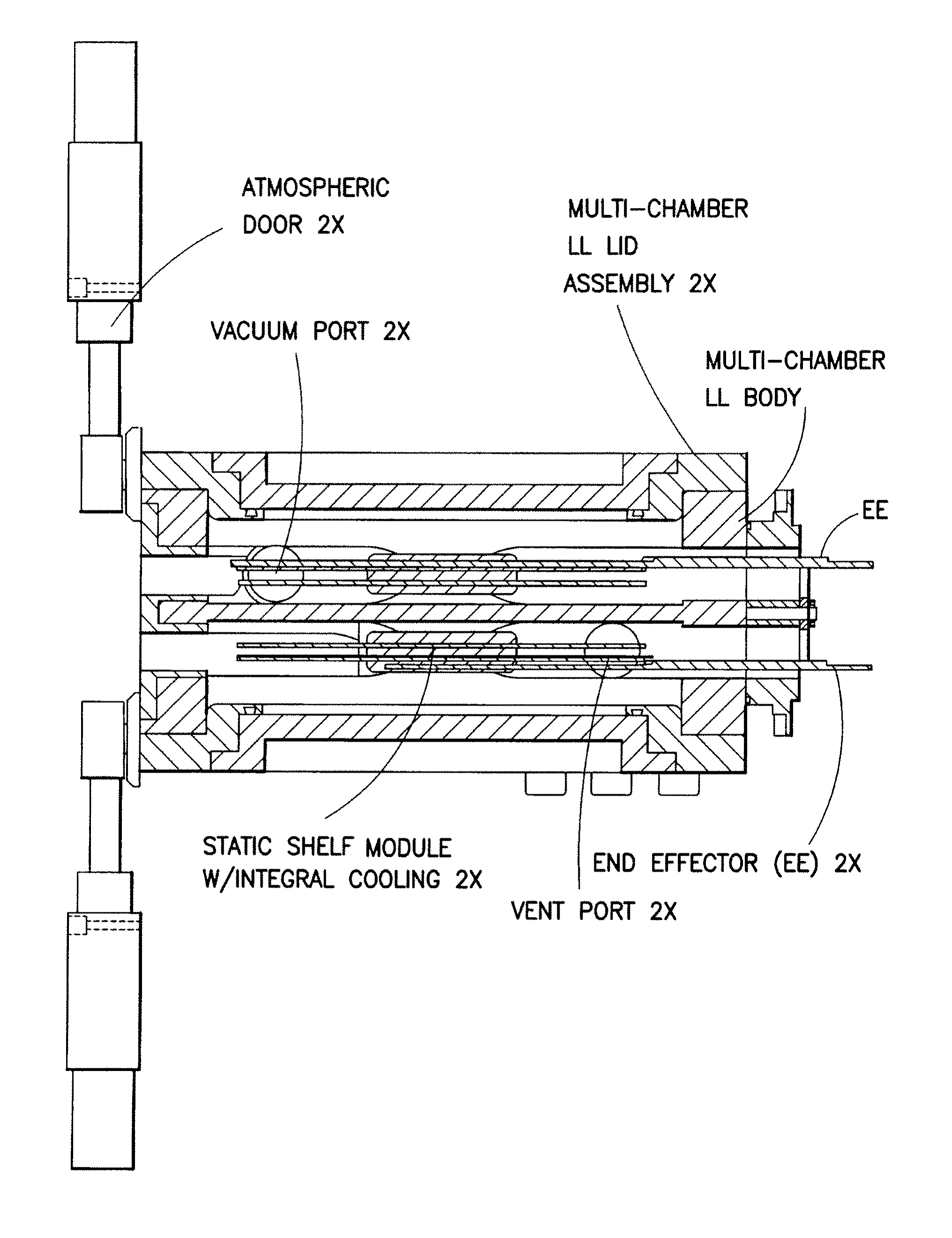
[0013]In accordance with a first exemplary embodiment a substrate processing tool in provided. The substrate processing tool includes a frame forming at least one isolatable chamber configured to hold a controlled atmosphere, at least two substrate supports located within each of the at least one isolatable chamber, each of the at least two substrate supports being stacked one above the other and configured to hold a respective substrate and a cooling unit communicably coupled to the at least two substrate supports such that the at least two substrate supports and cooling unit effect simultaneous conductive cooling of each of the respective substrates located on the at least two substrate supports.

BRIEF DESCRIPTION OF THE DRAWINGS

[0014]The foregoing aspects and other features of the exemplary embodiment are explained in the following description, taken in connection with the accompanying drawings, wherein:

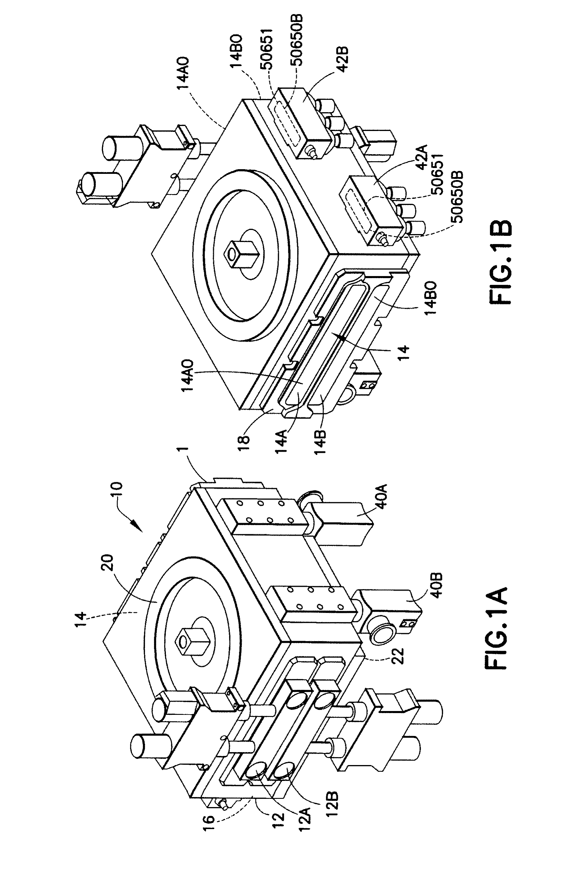
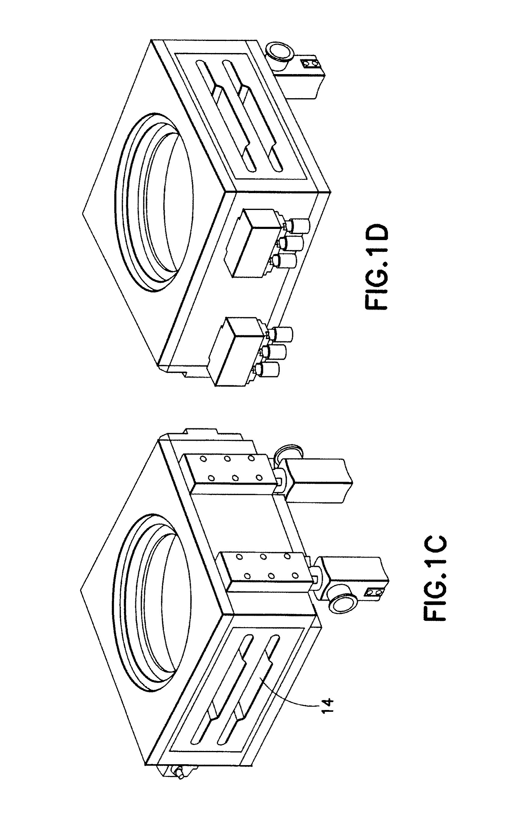
[0015]FIGS. 1A-1B are schematic perspective views of a substrate processing ch...


PUM


Abstract

A substrate processing tool including a frame forming at least one isolatable chamber configured to hold a controlled atmosphere, at least two substrate supports located within each of the at least one isolatable chamber, each of the at least two substrate supports being stacked one above the other and configured to hold a respective substrate and a cooling unit communicably coupled to the at least two substrate supports such that the at least two substrate supports and cooling unit effect simultaneous conductive cooling of each of the respective substrates located on the at least two substrate supports.

Description

CROSS-REFERENCE TO RELATED APPLICATION(S)[0001]This application claims the benefit of U.S. Provisional Patent Application No. 60 / 938,922, filed on May 18, 2007, the disclosure of which is incorporated by reference herein in its entirety.BACKGROUND[0002]1. Field[0003]The exemplary embodiments generally relate to controlled atmosphere environments and, more particularly, to increasing throughput in those environments.[0004]2. Brief Description of Related Developments[0005]Increased efficiencies are sought in the production electronics, and particularly in the production of semiconductor devices that form an even increasing part of electronics.[0006]To optimize throughput of hot wafers using static loadlock cooling shelves, through a cluster tool while minimizing the part count and complexity of the assembly, particularly eliminating any motion / device inside the loadlock. To achieve higher throughputs in a cluster tool, multiple loadlocks modules are used conventionally. This increases...

Claims


Application Information

Patent Timeline
Patent Type & Authority Patents(United States)
IPC IPC(8): B65G49/07
CPCH01L21/67126H01L21/67098H01L21/67201H01L21/6719H01L21/67742H01L21/68707
Inventor HOFMEISTER, CHRISTOPHERELLIOT, MARTIN R.KRUPYSHEV, ALEXANDERHALLISEY, JOSEPHKRAUS, JOSEPH A.FOSNIGHT, WILLIAMCARBONE, CRAIG J.BLAHNIK, JEFFREY C.FONG, HO YIN OWEN
Owner BOOKS AUTOMATION US LLC
Why Eureka
Try Eureka