Sensor interface for wireless control

a wireless control and sensor technology, applied in the field of wireless control, can solve the problems of inflexibility, difficulty and expense of retrofitting for change, new wireless sensors, and costing some installations

Active Publication Date: 2012-09-25
ABL IP HLDG
View PDF172 Cites 107 Cited by
  • Summary
  • Abstract
  • Description
  • Claims
  • Application Information

AI Technical Summary

Problems solved by technology

Issues with such a scheme may include inflexibility and difficulty and expense associated with retrofitting for changing and / or growing installations.
While wireless control solutions may allow for increased flexibility, implementing wireless solutions may include installing new wireless sensors, which may be costly for some installations.

Method used


Image

  • Sensor interface for wireless control
  • Sensor interface for wireless control
  • Sensor interface for wireless control

Examples


Embodiment Construction

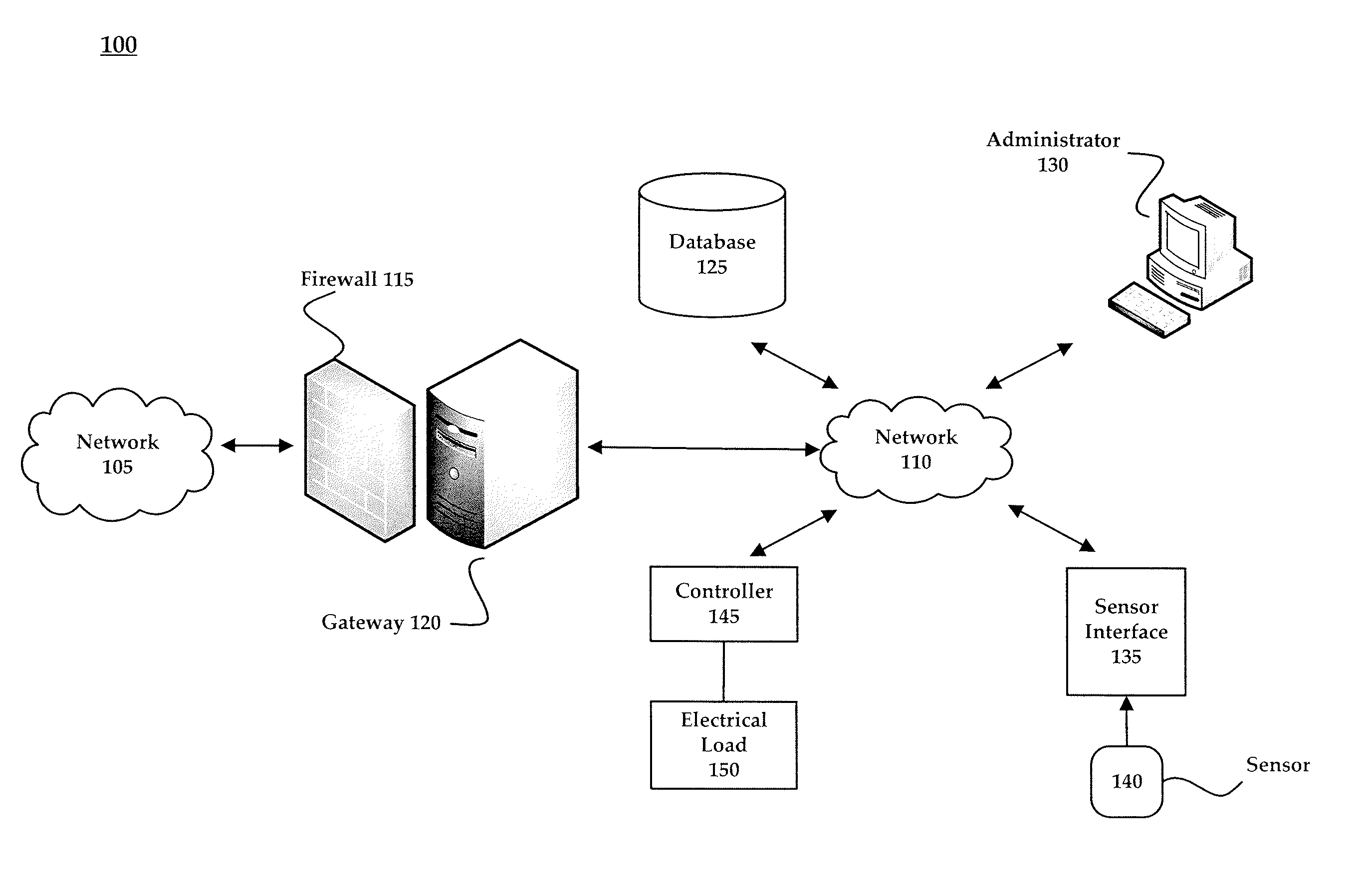
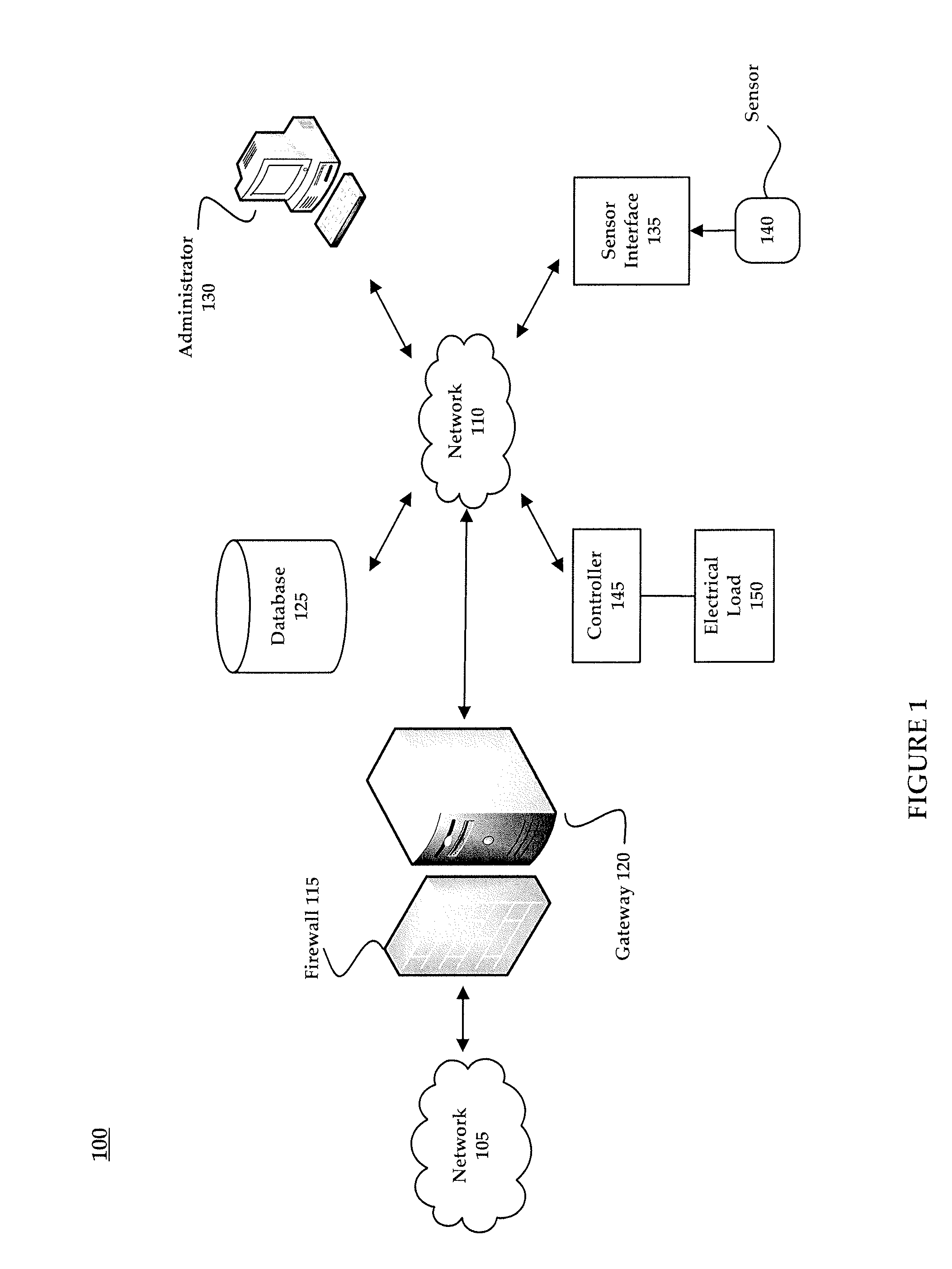
[0019]The present invention provides systems and methods for enabling wireless communication with a wired sensor. These systems and methods may be used to retrofit building installations by adapting pre-existing, wired sensors for wireless communication with wireless control systems. A sensor interface may be communicatively coupled with a sensor that provides information about a detected environmental condition. The sensor interface may wirelessly transmit information received from the sensor to a controller that may control an electrical load device based on the wirelessly transmitted information. Controlling an electrical load device, for example, may allow a building owner or facility manager to adapt to changing conditions and optimize operation of electrical load devices (e.g., lighting, room temperature), thereby reducing waste and energy costs.

[0020]FIG. 1 is a network environment 100 in which may be implemented an exemplary system for enabling wireless communication with a ...


PUM


Abstract

Systems and methods for enabling communication with a wired sensor are provided. A wired sensor may be adapted for wireless communication using a sensor interface. A sensor interface is communicatively coupled with a wired sensor that provides information about a detected environmental condition. The sensor interface wirelessly transmits information received from the wired sensor to a controller that may control an electrical load based on the wirelessly transmitted information.

Description

CROSS-REFERENCE TO RELATED APPLICATION[0001]This application claims the priority benefit of U.S. provisional application No. 61 / 258,845 filed Nov. 6, 2009 and U.S. provisional application No. 61 / 258,841 filed Nov. 6, 2009, the disclosures of which are incorporated herein by reference.[0002]This application is also related to U.S. patent application Ser. No. 12 / 156,621 filed Jun. 2, 2008 and U.S. patent application Ser. No. 12 / 380,727 filed Mar. 2, 2009, the disclosures of which are also incorporated herein by reference.BACKGROUND OF THE INVENTION[0003]1. Field of the Invention[0004]The present invention generally involves wireless control. More specifically, the present invention relates to a sensor interface for enabling wireless communication with a wired sensor.[0005]2. Description of Related Art[0006]In recent years, a growing concern over environmental responsibility and viability has prompted various measures to reduce energy consumption and ensuing costs. In commercial and re...

Claims


Application Information

Patent Timeline
Patent Type & Authority Patents(United States)
IPC IPC(8): G05B11/01G05B15/00
CPCG05B15/02G01N21/255G01V8/20G01N21/27G01N2021/1793H05B47/11H05B47/115Y02B20/40
Inventor HUIZENGA, CHARLESCORR, MICHAEL G.PATON, JOHN DOUGLAS
Owner ABL IP HLDG
Why Eureka
Try Eureka