
Building control system with remote control unit and methods of operation

a technology of remote control unit and building control system, which is applied in the field of remote control unit sensing and control, can solve the problems that the environmental conditions sensed by the sensors often do not accurately represent the actual environmental conditions at the location of the occupants

Active Publication Date: 2012-10-02
ADEMCO INC
View PDF37 Cites 62 Cited by
  • Summary
  • Abstract
  • Description
  • Claims
  • Application Information

AI Technical Summary

Benefits of technology

The present invention is about a building control system that includes a HVAC controller and a remote control unit. The invention provides methods for controlling the comfort level of the building or other structure by using the first and second temperatures sensed by the first and second controllers, respectively. The control module of the first controller can control the comfort level of the building based on either the first or second temperature, or a combination of both. The invention also includes a wireless interface that allows the second controller to communicate the second temperature to the first controller. The control module of the first controller can use the second temperature to control the comfort level of the building, and if a condition is detected, it can switch to using the first temperature. The invention provides innovative features such as sensing and controlling the temperature of the building using a thermostat and a portable remote controller, and displaying the temperature on the user interface of the controllers.

Problems solved by technology

In many cases, the occupants of the building do not occupy the space immediately adjacent to the sensors, and therefore, the environmental conditions sensed by the sensors often do not accurately represent the actual environmental conditions at the location of the occupants.

Method used


Image

  • Building control system with remote control unit and methods of operation
  • Building control system with remote control unit and methods of operation
  • Building control system with remote control unit and methods of operation

Examples


Embodiment Construction

[0015]The following description should be read with reference to the drawings wherein like reference numerals indicate like elements throughout the several views. The detailed description and drawings show several embodiments which are meant to be illustrative of the claimed invention.

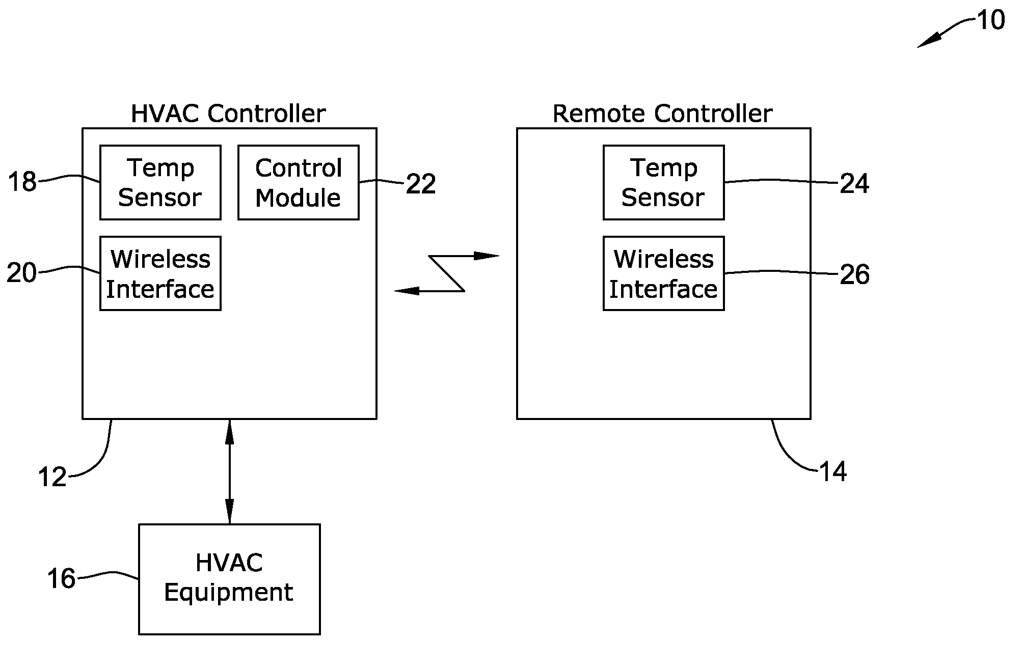
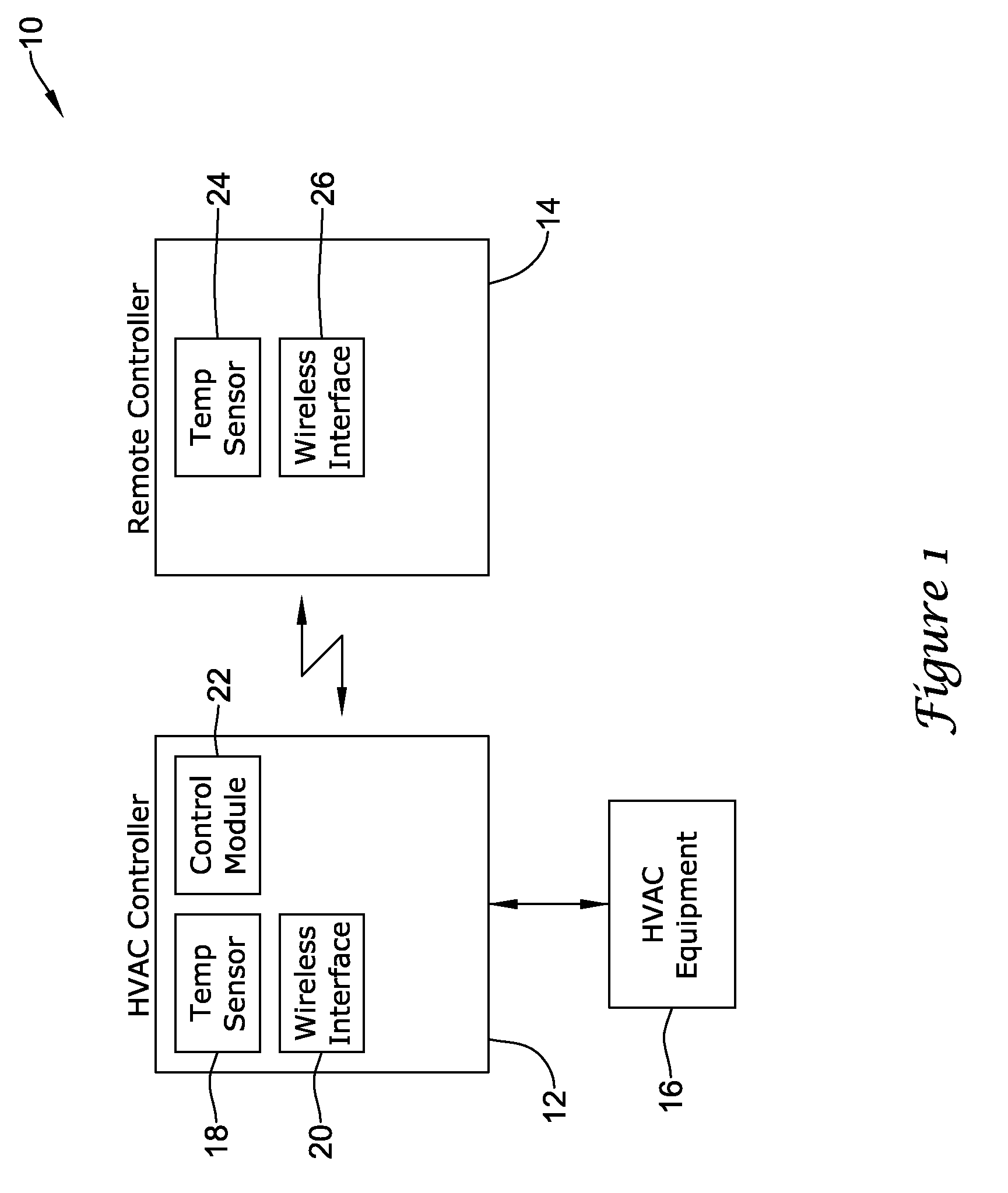
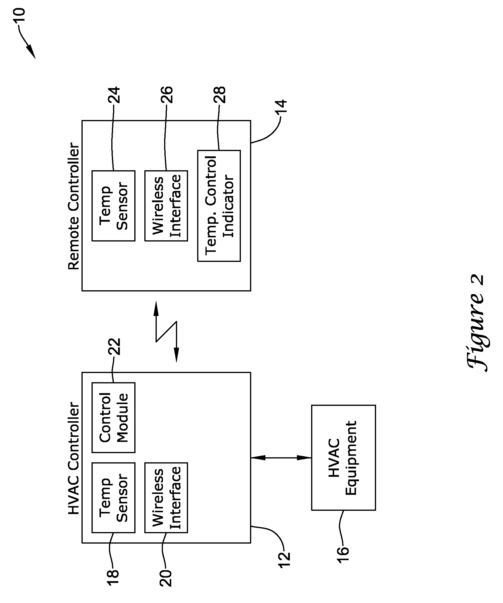
[0016]FIG. 1 is a block diagram of an illustrative embodiment of a building control system 10. In the illustrative embodiment, building control system 10 may include a heating, ventilation, and air conditioning (HVAC) controller 12, HVAC equipment 16 having one or more HVAC system components, and a remote controller 14. In the illustrative embodiment, HVAC controller 12 may be operatively connected in any suitable manner to HVAC equipment 16, such as one or more HVAC system components of HVAC equipment 16, which can be activated to regulate one or more environmental conditions such as temperature, humidity, ventilation, and air quality levels within a building or structure. Example HVAC equipment 16 ma...


PUM


Abstract

A building controller for controlling the comfort level in a building is described. The building controller may include a thermostat and wireless remote controller for communicating with the thermostat from a remote location. The thermostat may have access to a first temperature sensor for sensing a first temperature, sometimes at or near the thermostat. The remote controller may likewise have a second temperature sensor for sensing a second temperature, sometimes at or near the remote controller. Under some conditions, the thermostat may use the second temperature sensed by the remote controller to control the comfort level in a building unless or until a predetermined condition is detected, after which the thermostat may use a different temperature, such as the first temperature at or near the thermostat, to control the comfort level in a building.

Description

FIELD[0001]The present invention relates generally to building control systems that include an HVAC controller as well as a remote control unit, and more particularly, to devices and methods for remote control unit sensing and control in such building control systems.BACKGROUND[0002]Building control systems often include heating, ventilation, and / or air conditioning (HVAC) systems to control the comfort level within a building. Many building control systems include a controller that activates and deactivates one or more HVAC components of the HVAC system to affect and control one or more environmental conditions within the building. These environmental conditions can include, but are not limited to, temperature, humidity, and / or ventilation. In many cases, the controller of the building control system may include, or have access to, one or more sensors, and may use parameters provided by the one or more sensors to control the one or more HVAC components to achieve one or more progra...

Claims


Application Information

Patent Timeline
Patent Type & Authority Patents(United States)
IPC IPC(8): G05D23/00
CPCG05D23/1934
Inventor STONER, MARCUS D.SCHNELL, ROBERT J.SCHULTZ, DAVID A.LEEN, CARY
Owner ADEMCO INC
Learn More