
Lithium ion secondary battery

a secondary battery and lithium ion technology, applied in the field of lithium ion secondary batteries, can solve the problems of affecting the charge/discharge characteristic of negative-electrode active materials capable of forming lithium alloys, such as silicon, and the volume change of negative-electrode active materials, so as to prevent electrical short circuits and reduce the effect of charge/discharge characteristics

Active Publication Date: 2012-10-02
PANASONIC ENERGY CO LTD
View PDF8 Cites 8 Cited by
  • Summary
  • Abstract
  • Description
  • Claims
  • Application Information

AI Technical Summary

Benefits of technology

[0011]The present invention has been made in view of the foregoing points. Therefore, an object of the present invention is that a cylindrical lithium ion secondary battery using a negative-electrode active material capable of forming an alloy with lithium effectively prevents electrical short circuit between the positive and negative electrodes while preventing or reducing deterioration of the charge / discharge characteristic due to expansion of the spirally wound electrode assembly.

Problems solved by technology

In recent years, power consumption of mobile devices including cellular phones, notebook computers and personal digital assistants (PDAs) has rapidly increased.
However, if a graphite material, which has been widely used so far, is used as a negative-electrode active material for a lithium ion secondary battery, a problem arises in that it is difficult to sufficiently increase the capacity of the lithium ion secondary battery.
However, negative-electrode active materials capable of forming an alloy with lithium, such as silicon, change the volume with storage and release of lithium.
Therefore, if a cylindrical battery having a substantially unchanged volume is produced using a negative-electrode active material capable of forming an alloy with lithium, a volume change of the negative-electrode active material may cause a bend or the like in a central region of the spirally wound electrode assembly.
If a bend or the like occurs in the electrode assembly, the separator may be damaged and the positive and negative electrodes may be electrically short-circuited.
As a result, the stress in the electrode assembly is increased, which may cause the separator to clog or cause the electrolytic solution to be extruded from the electrode assembly.
Hence, if a center pin is inserted into the center of the spirally wound electrode assembly, a good charge / discharge characteristic may not be provided.
However, if the center pin does not come into contact with the inner periphery of the spirally wound electrode assembly, the spirally wound electrode assembly may not suitably urge the center pin upon expansion of the negative-electrode active material.
Thus, the center pin cannot sufficiently prevent the deformation of the spirally wound electrode assembly, resulting in electrical short circuit between the positive and negative electrodes.

Method used


Image

  • Lithium ion secondary battery
  • Lithium ion secondary battery
  • Lithium ion secondary battery

Examples


first embodiment

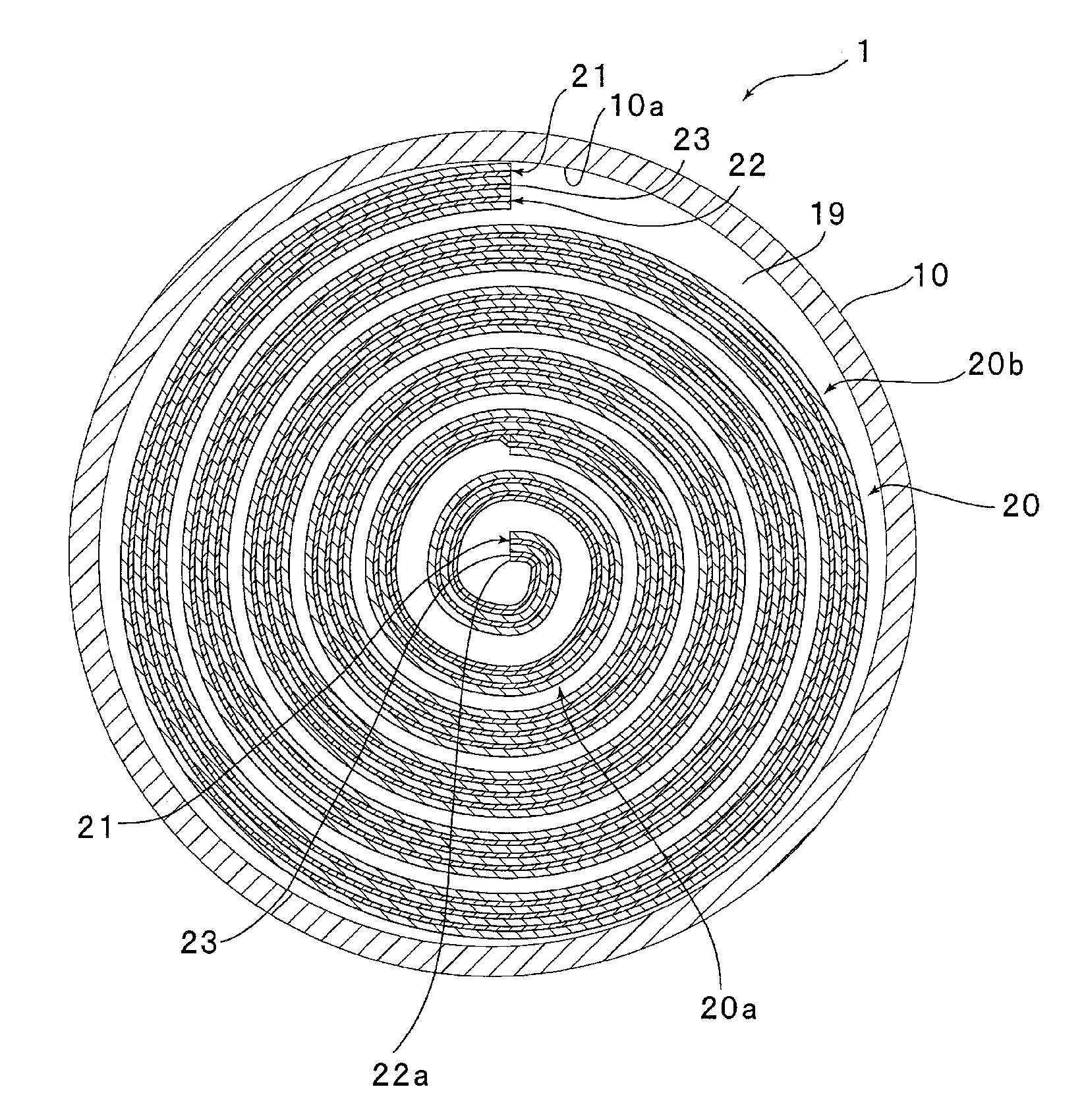
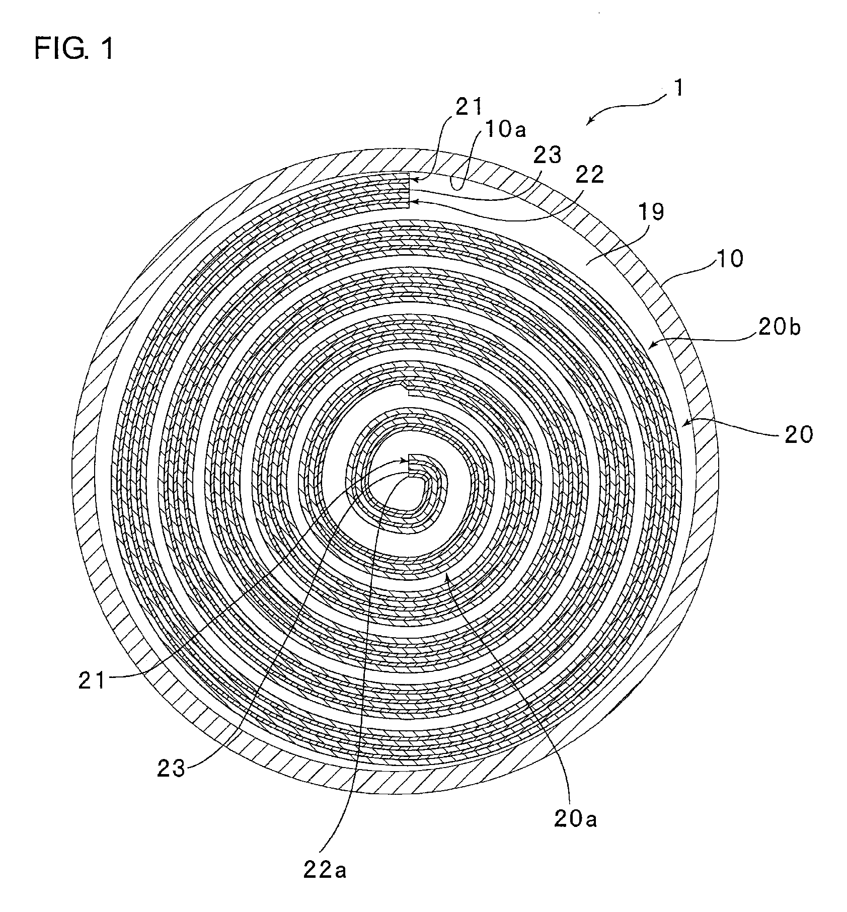
[0028]FIG. 1 is a schematic transverse cross-sectional view of a lithium ion secondary battery 1 according to this embodiment. Note that for convenience of drawing, the number of winding turns of the spirally wound electrode assembly in FIG. 1 is smaller than in reality. Furthermore, for convenience of drawing, each figure is represented as if a clearance existed between radially adjacent portions of the spirally wound electrode assembly. Actually, however, radially adjacent portions of the spirally wound electrode assembly are in contact with each other. Each figure is also represented as if a clearance also existed between the spirally wound electrode assembly and the urging part. Actually, however, the spirally wound electrode assembly and the urging part are located radially in contact with each other.

[0029]As shown in FIG. 1, the lithium ion secondary battery 1 includes a battery container 10. The battery container 10 is formed into an approximately cylindrical shape closed at ...

example 1

[0093]In Example 1, a cylindrical lithium ion secondary battery was produced using a negative electrode, a positive electrode and a nonaqueous electrolytic solution produced in the following manners. The produced lithium ion secondary battery was 12.8 mm in diameter and 37.7 mm in height.

[0094][Production of Negative Electrode]

[0095]First, a negative-electrode active material was produced in the following manner. A silicon core placed in a reduction furnace was heated to 800° C. by ohmic heating. Thereafter, a gas mixture of high-purity silane gas SiH4 and hydrogen gas was supplied into the reduction furnace to precipitate polycrystalline silicon on the surface of the silicon core, thereby producing a polycrystalline silicon mass. The polycrystalline silicon mass was ground and classified, thereby producing polycrystalline silicon particles having a purity of 99%. In this example, the polycrystalline silicon particles thus obtained were used as a negative-electrode active material. ...

examples 2 to 4

[0116]Lithium ion secondary batteries were produced and evaluated in the same manners as in Example 1 except that the respective numbers of winding turns of their urging parts were those shown in TABLE 1.


PUM

PropertyMeasurementUnit
thicknessaaaaaaaaaa
thicknessaaaaaaaaaa
diameteraaaaaaaaaa

Abstract

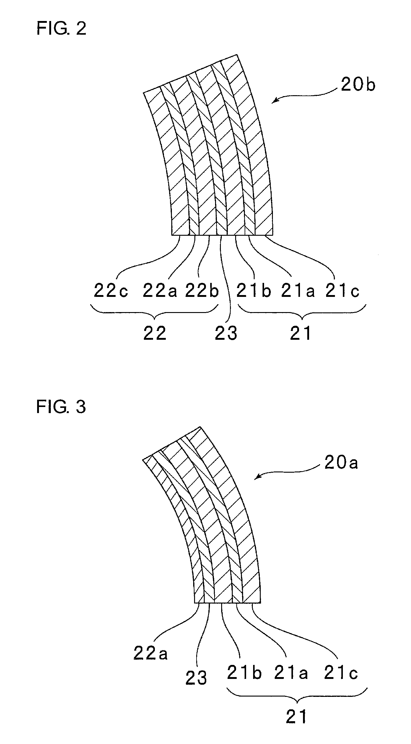
A lithium ion secondary battery 1 includes a spirally wound electrode assembly 20 and a cylindrical battery container 10. The spirally wound electrode assembly 20 includes a negative electrode 21, a positive electrode 22 and a separator 23. The negative electrode 21 includes negative-electrode active material layers 21b and 21c containing a negative-electrode active material capable of forming an alloy with lithium. The lithium ion secondary battery 1 includes an urging part 20a. The urging part 20a is disposed in the center of and in contact with the spirally wound electrode assembly 20. The urging part 20a is contractible in diameter. The urging part 20a is configured to urge the spirally wound electrode assembly 20 radially outward at least when contracting in diameter.

Description

BACKGROUND OF THE INVENTION[0001]1. Field of the Invention[0002]This invention relates to lithium ion secondary batteries and particularly relates to cylindrical lithium ion secondary batteries using a negative-electrode active material capable of forming an alloy with lithium.[0003]2. Description of Related Arts[0004]In recent years, power consumption of mobile devices including cellular phones, notebook computers and personal digital assistants (PDAs) has rapidly increased. Along with this, there has been an increasing demand to increase the capacity of lithium ion secondary batteries. However, if a graphite material, which has been widely used so far, is used as a negative-electrode active material for a lithium ion secondary battery, a problem arises in that it is difficult to sufficiently increase the capacity of the lithium ion secondary battery. In view of this problem, studies have been actively conducted on negative-electrode active materials having higher capacities than g...

Claims


Application Information

Patent Timeline
Patent Type & Authority Patents(United States)
IPC IPC(8): H01M2/16H01M50/119
CPCH01M2/0225H01M2/0285H01M4/661H01M10/052H01M10/0587H01M4/134H01M2/022Y02E60/122Y02E60/10H01M50/56H01M50/107Y02P70/50H01M50/119H01M10/0468H01M10/0525H01M50/538
Inventor KOBAYASHI, KEITAKANO, YASUOSUNANO, TAIZOUKAMINO, MARUO
Owner PANASONIC ENERGY CO LTD
Learn More