Electrically tunable fabry-perot interferometer, an intermediate product an electrode arrangement and a method for producing an electrically tunable fabry-perot interferometer

a technology of fabryperot and fabryperot interferometer, which is applied in the direction of instruments, optical elements, plasma techniques, etc., can solve the problems of increasing the complicity of the production process, increasing the sacrificial layer, and increasing the production cost, so as to prevent electrical short circuits and reduce the complexity of the interferometer production process , the effect of improving the reliability of the structur

Inactive Publication Date: 2011-11-17
TEKNOLOGIAN TUTKIMUSKESKUS VTT
View PDF8 Cites 37 Cited by
  • Summary
  • Abstract
  • Description
  • Claims
  • Application Information

AI Technical Summary

Benefits of technology

[0035]In one embodiment of the invention the electrodes of the movable mirror structure are covered by electrically isolating or semi-insulating optical layer(s), which protects the electrodes and prevents electrical short circuits of the opposite electrodes. If electrically semi-insulating layer, such as TiO2, is used for covering the electrode surface it will also prevent electrical charging phenomena at the surfaces of the electrodes. Charging of the optical layer may cause inaccuracy of the controlled mirror position.
[0036]In one aspect of the invention one of the electrodes is electrically floating. This allows the use of alternating voltage for the tuning of the interferometer, and it is not necessary to provide control conductors to one of the mirrors for controlling the gap between the mirrors. The production process of the interferometer is less complicated, and the structure is more reliable when it is not necessary to arrange electrical connections to all electrode layers. This floating electrode structure can be advantageous also in electrically tunable Fabry-Perot interferometers where other than polymer material is used as a sacrificial layer. The floating electrode structure can also be used in other components than interferometers, such as adjustable capacitors. The electrically floating electrode can be an electrode of a movable part or an electrode of a fixed part in the structure of a component. When the electrically floating electrode is located in the upper mirror of an interferometer, the number of lithography phases after applying the polymer layer can be minimized.

Problems solved by technology

However, there are some disadvantages related with the prior art solutions for production of interferometers and the interferometer components.
The doping of the silicon layers requires the use of an ion doping facility, which is expensive equipment and thus increases the production cost.
Another problem relates to removing the sacrificial layer between the mirrors.
Such a separate process increases the complicity of the production process.
Due to the relatively high production cost of interferometers, it has not been possible to use them in mass product applications where the cost requirements are strict.
A further disadvantage of the prior art technology relates to the inability to provide a gap with short distance between the mirrors.
This is due to the wet etching process wherein providing narrow gaps is difficult.
Such membranes easily become damaged during wet etching.
Therefore the prior art technology is not suitable for producing electrically tunable Fabry-Perot interferometers for short wavelengths such as visible and ultraviolet range.

Method used


Image

  • Electrically tunable fabry-perot interferometer, an intermediate product an electrode arrangement and a method for producing an electrically tunable fabry-perot interferometer
  • Electrically tunable fabry-perot interferometer, an intermediate product an electrode arrangement and a method for producing an electrically tunable fabry-perot interferometer
  • Electrically tunable fabry-perot interferometer, an intermediate product an electrode arrangement and a method for producing an electrically tunable fabry-perot interferometer

Examples


Embodiment Construction

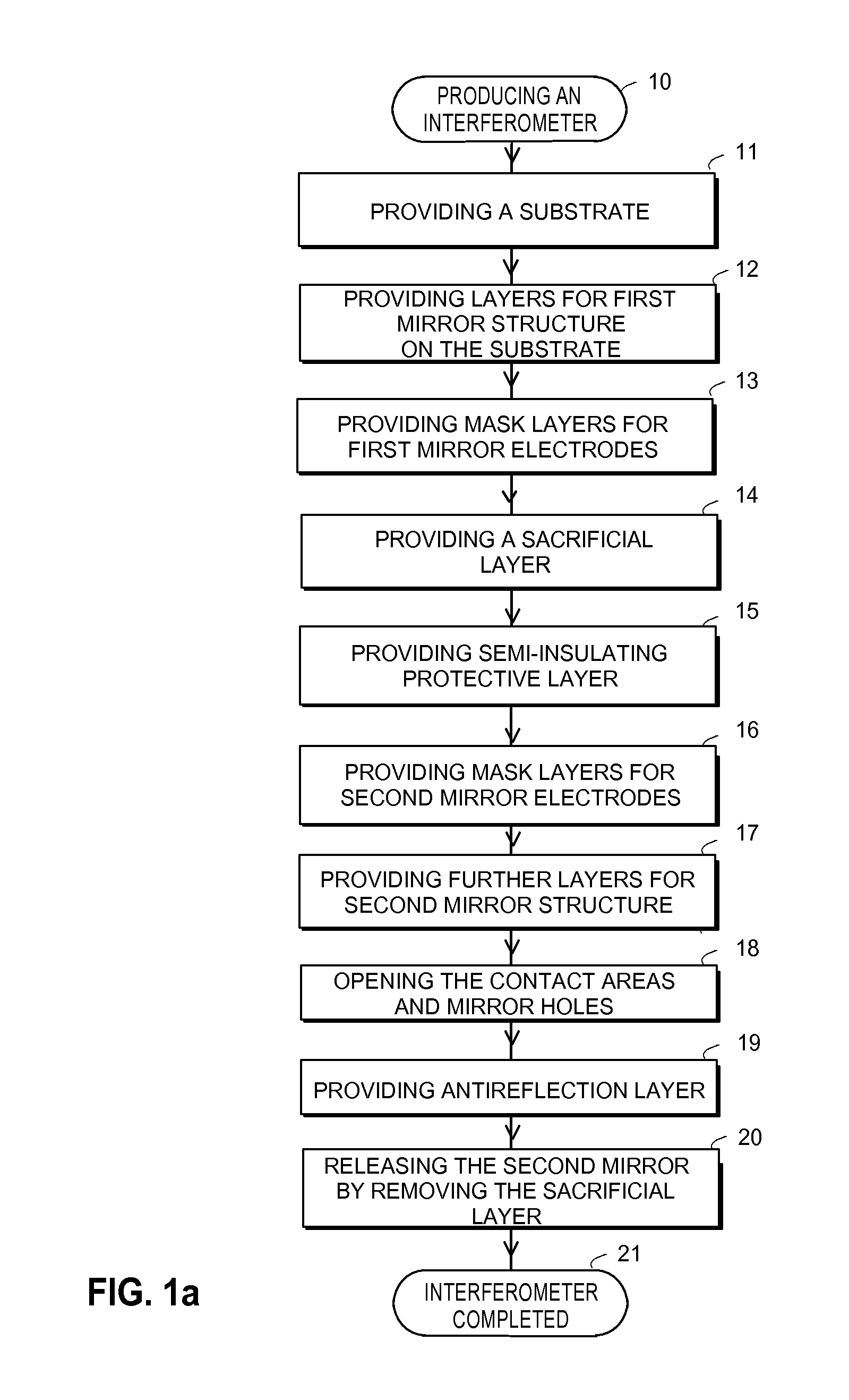
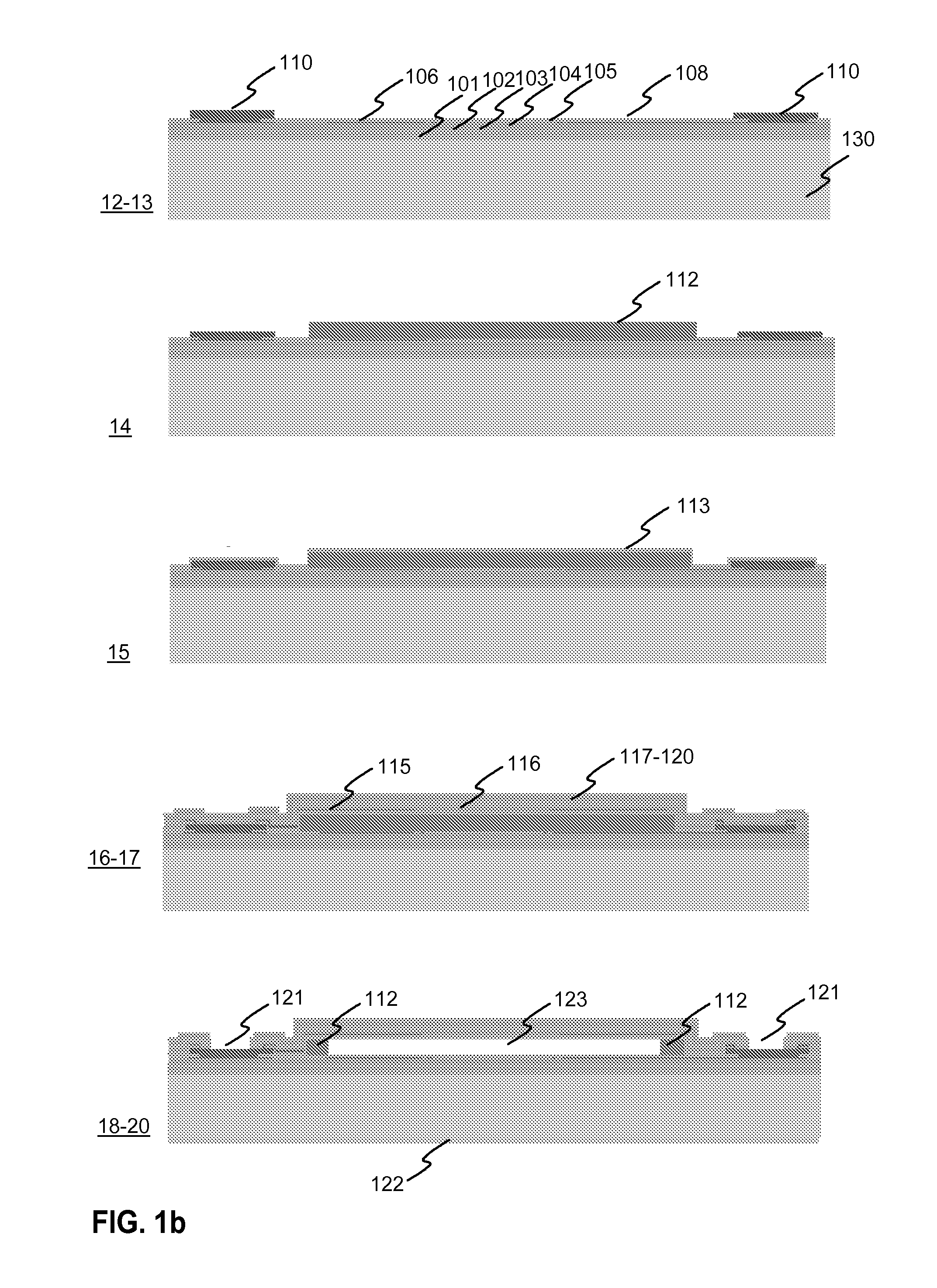
[0055]FIG. 1a illustrates a process diagram of an exemplary method according to the invention for producing an electrically tunable Fabry-Perot interferometer. FIG. 1b illustrates cross sections of the product after certain production phases of FIG. 1a.

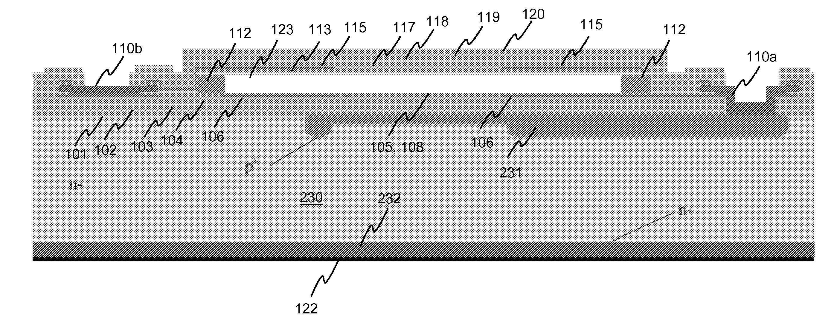
[0056]The production process is started by providing a wafer 100 in phase 11. The wafer material can be e.g. fused silica. In the next phase 12 layers 101-105, 108 are formed for providing layers of the first, fixed mirror structure on the substrate. The first mirror structure can be produced by e.g. depositing successive layers of titanium dioxide TiO2 and aluminium oxide Al2O3 on the substrate, phase 12. For example, there may be two layers of aluminium oxide 102, 104 between three layers of titanium dioxide 101, 103, 105. The thickness of the titanium dioxide layers can be e.g. 10 nm-2 μm, and the thickness of the aluminium oxide layers can be e.g. 10 nm-2 μm. The actual thickness of the layers depends on the materials and the ran...


PUM

PropertyMeasurementUnit
temperaturesaaaaaaaaaa
thicknessaaaaaaaaaa
temperatureaaaaaaaaaa

Abstract

Electrically tunable Fabry-Perot interferometers which are produced with micromechanical (MEMS) technology. Producing interferometers with prior art processes includes costly and complicated production phases. Therefore, it has not been possible to apply interferometers in consumer mass products. According to the present solution, the Fabry-Perot cavity is made by removing a sacrificial layer (112) which has been polymer material. A mirror layer (113, 117-120) which is produced above the sacrificial layer can be made with atomic layer deposition technology, for example. According to a preferable embodiment, electrodes (106b, 115b) of the mirror structures are formed by using sputtering or evaporation. With the present solution it is possible to avoid the above mentioned problems related with prior art.

Description

TECHNICAL FIELD [0001]The invention relates to a method for producing an electrically tunable Fabry-Perot interferometer, an electrically tunable Fabry-Perot interferometer, an intermediate product, and an electrode arrangement. More specifically, the invention relates to electrically tunable Fabry-Perot interferometers which are produced with micromechanical (MEMS) technology. The technical field of the invention is specified in the preamble of the independent claims.BACKGROUND TECHNOLOGY [0002]Fabry-Perot interferometers are used as optical filters and in spectroscopic sensors, for example. The Fabry-Perot interferometer is based on parallel mirrors, whereby a Fabry-Perot cavity is formed into a gap between the mirrors. The pass band wavelength of a Fabry-Perot interferometer can be controlled by adjusting the distance between the mirrors i.e. the width of the gap. The tuning is usually made electrically. It is common to use micromechanical technology for producing electrically tu...

Claims


Application Information

Patent Timeline
Patent Type & Authority Applications(United States)
IPC IPC(8): G01B9/02B05D5/06C23C14/34G02B26/00B05D5/12
CPCG02B26/001G01J3/26G02B5/284G02B26/00
Inventor BLOMBERG, MARTTIKATTELUS, HANNUPUURUNEN, RIIKKA
Owner TEKNOLOGIAN TUTKIMUSKESKUS VTT
Why Eureka
Try Eureka