Substrate carrying method and substrate carrying apparatus

a carrying method and substrate technology, applied in the direction of conveyor parts, emergency protective arrangements for limiting excess voltage/current, resistive material coating, etc., can solve the problem of reducing the yield or quality, the effect of preventing the recent growth in size of the glass substrate from electrical charging

Inactive Publication Date: 2006-09-14
SEIKO EPSON CORP
View PDF8 Cites 0 Cited by
  • Summary
  • Abstract
  • Description
  • Claims
  • Application Information

AI Technical Summary

Benefits of technology

[0013] By this configuration, even if a substrate during the carriage becomes electrically charged, it can be prevented that the substrate is charged with electricity since the charge is quickly lost through the conductive layer and the substrate supporting unit. Accordingly, since problems caused by the electrical charges on the substrate, for example, the destruction of TFT elements or absorption of dust in the air can be prevented, the yield and quality of the product can be improved. Especially, since the substrate supporting unit comes in contact with the conductive layer and the whole conductive layer is grounded, large area is grounded. Therefore, since good effectiveness to remove the electrical charges is expected and further electrical charging on the substrate can be surely prevented, the above-referenced effects can be obtained on any condition.
[0014] According to the substrate carrying apparatus of an aspect of the invention, it is preferable that the substrate supporting unit is constituted by a roller that transfers the substrate by rolling. By this configuration, the substrate can be smoothly transferred by the substrate supporting unit in the simple structure. According to the substrate carrying apparatus of another aspect of the invention, it is preferable that the substrate supporting unit is constituted by an attaching part that attaches on the substrate by vacuum. By this configuration, the substrate can be transferred with being firmly held. According to the substrate carrying apparatus of a further aspect of the invention, it is preferable that the substrate supporting unit is constituted by a guide rail that guides the substrate. By this configuration, the structure of substrate supporting unit can be significantly simplified.

Problems solved by technology

Here, specifically, since a static electricity is generated by the electrical charging of the liquid panel in the manufacturing process, there is a problem that elements such as TFT is destructed, dust in the air is adsorbed, and thus yield or quality is decreased.
Therefore, the problem has become serious.
(for example, see JP-A-10-133229) In the technology of the JP-A-10-133229, it is not sufficient to prevent the glass substrate recently growing in size from the electrical charging.

Method used


Image

  • Substrate carrying method and substrate carrying apparatus
  • Substrate carrying method and substrate carrying apparatus
  • Substrate carrying method and substrate carrying apparatus

Examples


first embodiment

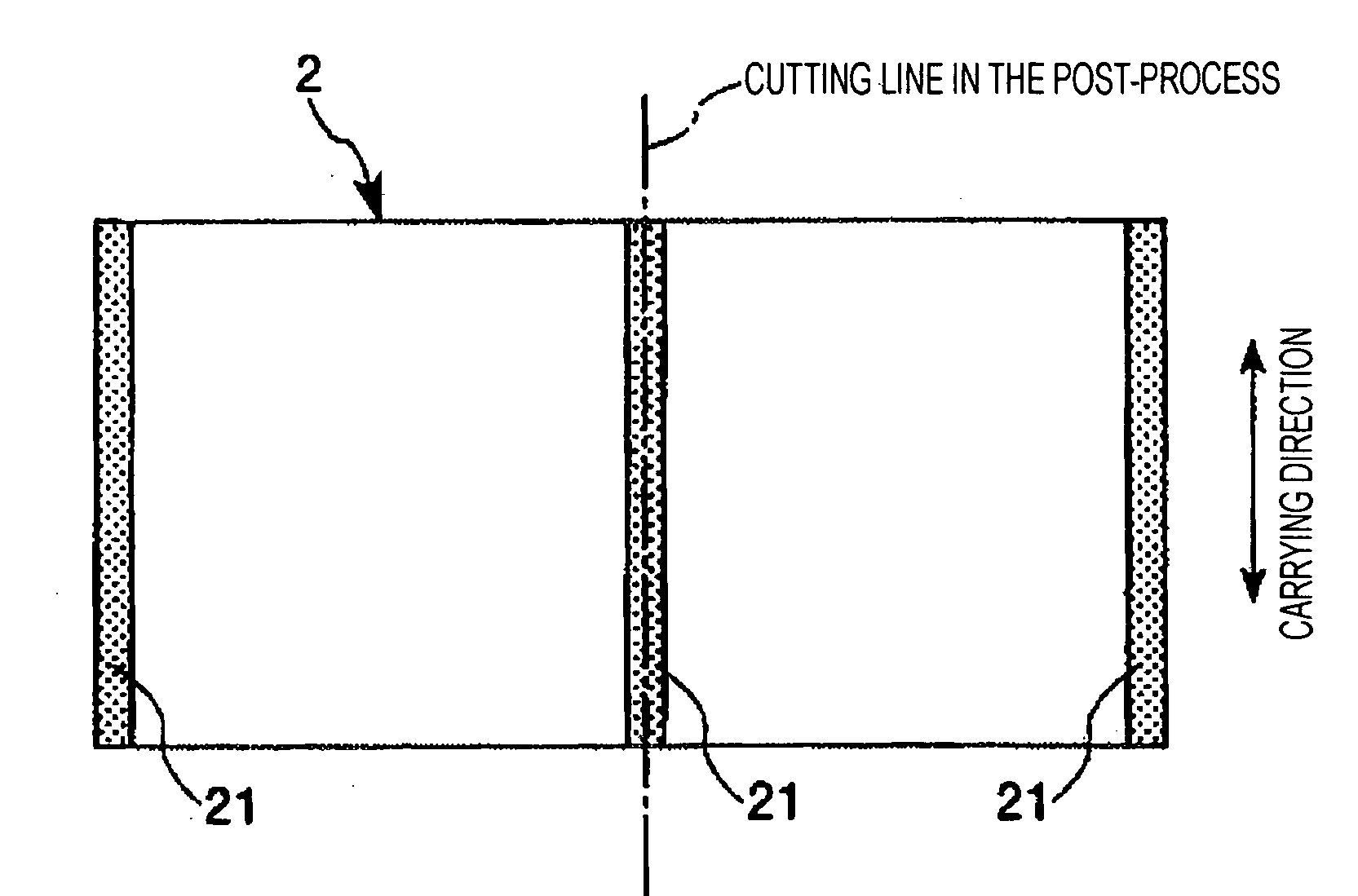
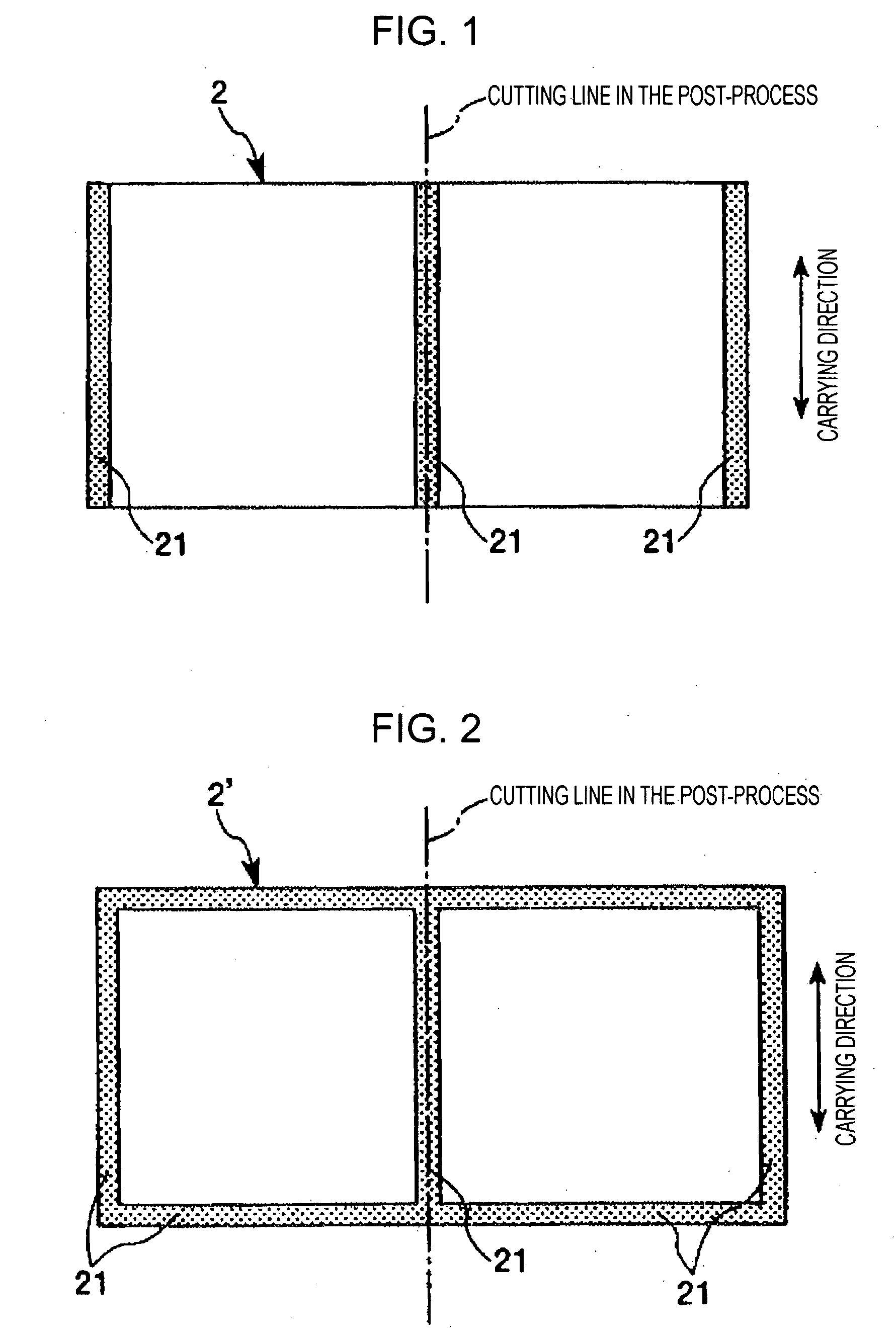
[0023]FIG. 1 is a view illustrating the bottom of the substrate when the substrate is carried as a carrying object according to the invention, and FIG. 2 is a view illustrating another configuration of the substrate which is a carrying object according to the invention. The substrate 2, the carrying object of the invention, is composed of the most part of insulating materials such as glass, plastic and so on. However, a part having conductivity like a circuit may be formed on the surface corresponding to the topside when the substrate 2 is carried.

[0024] Although the substrate 2 may be used for any purpose, the substrate 2 of the embodiment is a glass substrate to manufacture a liquid crystal panel.

[0025] Two liquid crystal panels for a big television screen are manufactured from the substrate 2. That is, the substrate 2 is cut into two pieces along the cutting line shown by a chain line in FIG. 1 in the process after carried by the substrate carrying method of the invention.

[002...

second embodiment

[0035]FIG. 6 is a front view illustrating the second embodiment of the substrate carrying apparatus that implements the substrate carrying method of the invention. Hereinafter, a second embodiment of the substrate carrying method and the substrate carrying apparatus of the invention will be described with reference to the figure. In the second embodiment, the differences from the above-mentioned embodiment are mainly explained and the same matters will be omitted.

[0036] The substrate carrying apparatus 1A shown in FIG. 6 corresponds to an apparatus having the same structure as the substrate carrying apparatus 1 of the first embodiment except for the point that the two rows excepting the central row among the three rows of the rollers 5 of the substrate carrying apparatus 1 are replaced with the guide rail 7a, 7b. In the substrate carrying apparatus 1A, the guide rail 7a, 7b also functions as the substrate supporting unit. When the substrate 2 is carried by the rolling of the roller...

third embodiment

[0038]FIG. 7 is a perspective view illustrating the third embodiment of the substrate carrying apparatus that implements the substrate carrying method of the invention. Hereinafter, a third embodiment of the substrate carrying method and the substrate carrying apparatus of the invention will be described with reference to FIG. 7. In the third embodiment, the differences from the above-mentioned embodiment are mainly explained and the same description will be omitted.

[0039] In FIG. 7, the substrate carrying apparatus 1B has the main body 4, the plural attaching parts 8 provided on the main body 4, and the transferring apparatus 9 carrying the main body 4. In the substrate carrying apparatus 1B, the attaching part 8 functions as the substrate supporting unit. The attaching part 8 is provided to protrude from the upper side of the main body 4. On the topside of the attaching part 8, the suction part 81 is formed. Inside the main body 4, a suction passage leading to each the suction pa...


PUM

PropertyMeasurementUnit
electrical chargesaaaaaaaaaa
conductivityaaaaaaaaaa
vacuumaaaaaaaaaa

Abstract

A substrate carrying method for removing the electrical charges on a substrate and then carrying the substrate includes forming a conductive layer with conductivity on a part of the surface of the substrate, and carrying the substrate while supporting a conductive layer-forming region of the substrate by a grounded substrate supporting unit with conductivity.

Description

BACKGROUND [0001] 1. Technical Field [0002] The present invention relates to a substrate carrying method and a substrate carrying apparatus. [0003] 2. Related Art [0004] In case that an active matrix type liquid crystal panel driving the liquid crystal as a switching element such as a liquid crystal panel, particularly TFT is manufactured, the manufacturing apparatus of the liquid crystal panel has been improved to obtain the enhancement of yield or quality. Here, specifically, since a static electricity is generated by the electrical charging of the liquid panel in the manufacturing process, there is a problem that elements such as TFT is destructed, dust in the air is adsorbed, and thus yield or quality is decreased. Recently, a glass substrate for manufacturing a liquid crystal panel grows in size, and thus total amount of the glass substrate as an insulator is increased. Therefore, the problem has become serious. [0005] When the glass substrate is carried, the technology support...

Claims


Application Information

Patent Timeline
Patent Type & Authority Applications(United States)
IPC IPC(8): G03G13/04
CPCG02F1/1333G02F1/13
Inventor KOYAMA, MINORU
Owner SEIKO EPSON CORP
Why Eureka
Try Eureka