Modular electronic ballast

a technology of electronic ballasts and modules, applied in the direction of instruments, light sources, electrical equipment, etc., to achieve the effect of reducing development costs

Inactive Publication Date: 2012-10-02
UNIVERSAL LIGHTING TECHNOLOGIES
View PDF11 Cites 6 Cited by
  • Summary
  • Abstract
  • Description
  • Claims
  • Application Information

AI Technical Summary

Benefits of technology

[0015]Typical development cycles for traditional non-modular ballast techniques take about nine to ten months. Using a modular ballast development technique in accordance with the present invention, the development expense can be reduced by approximately fifty percent where “known good” modules are used to configure a new product. The additional material costs are only on the order of two percent higher using this modular ballast approach.

Problems solved by technology

For these types of products, cost is a critical aspect of the design.

Method used


Image

  • Modular electronic ballast
  • Modular electronic ballast
  • Modular electronic ballast

Examples


Embodiment Construction

[0031]Throughout the specification and claims, the following terms take at least the meanings explicitly associated herein, unless the context dictates otherwise. The meanings identified below do not necessarily limit the terms, but merely provide illustrative examples for the terms. The meaning of “a,”“an,” and “the” may include plural references, and the meaning of “in” may include “in” and “on.” The phrase “in one embodiment,” as used herein does not necessarily refer to the same embodiment, although it may. The term “coupled” means at least either a direct electrical connection between the connected items or an indirect connection through one or more passive or active intermediary devices. The term “circuit” means at least either a single component or a multiplicity of components, either active and / or passive, that are coupled together to provide a desired function. The term “signal” means at least one current, voltage, charge, temperature, data or other signal.

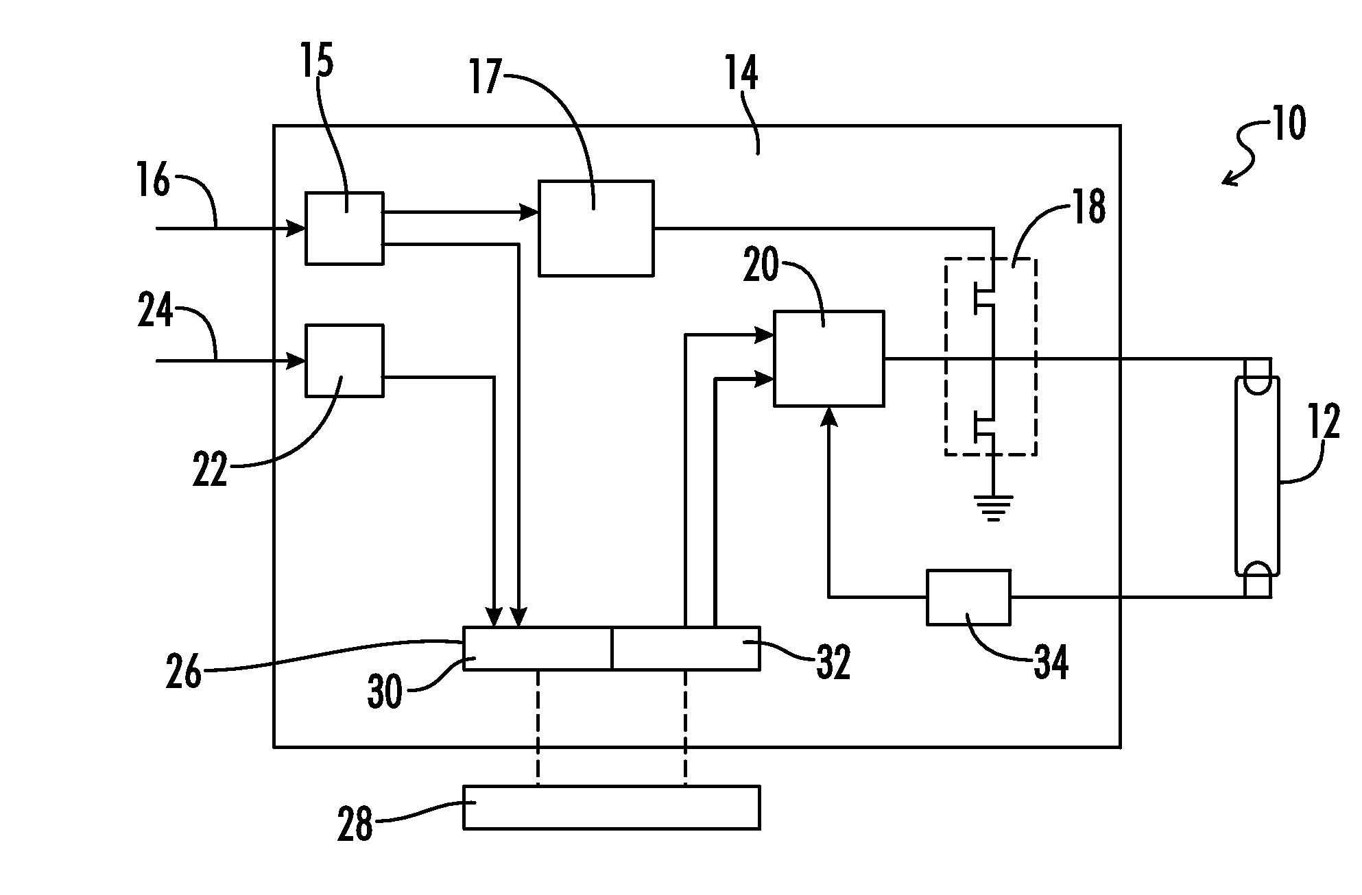
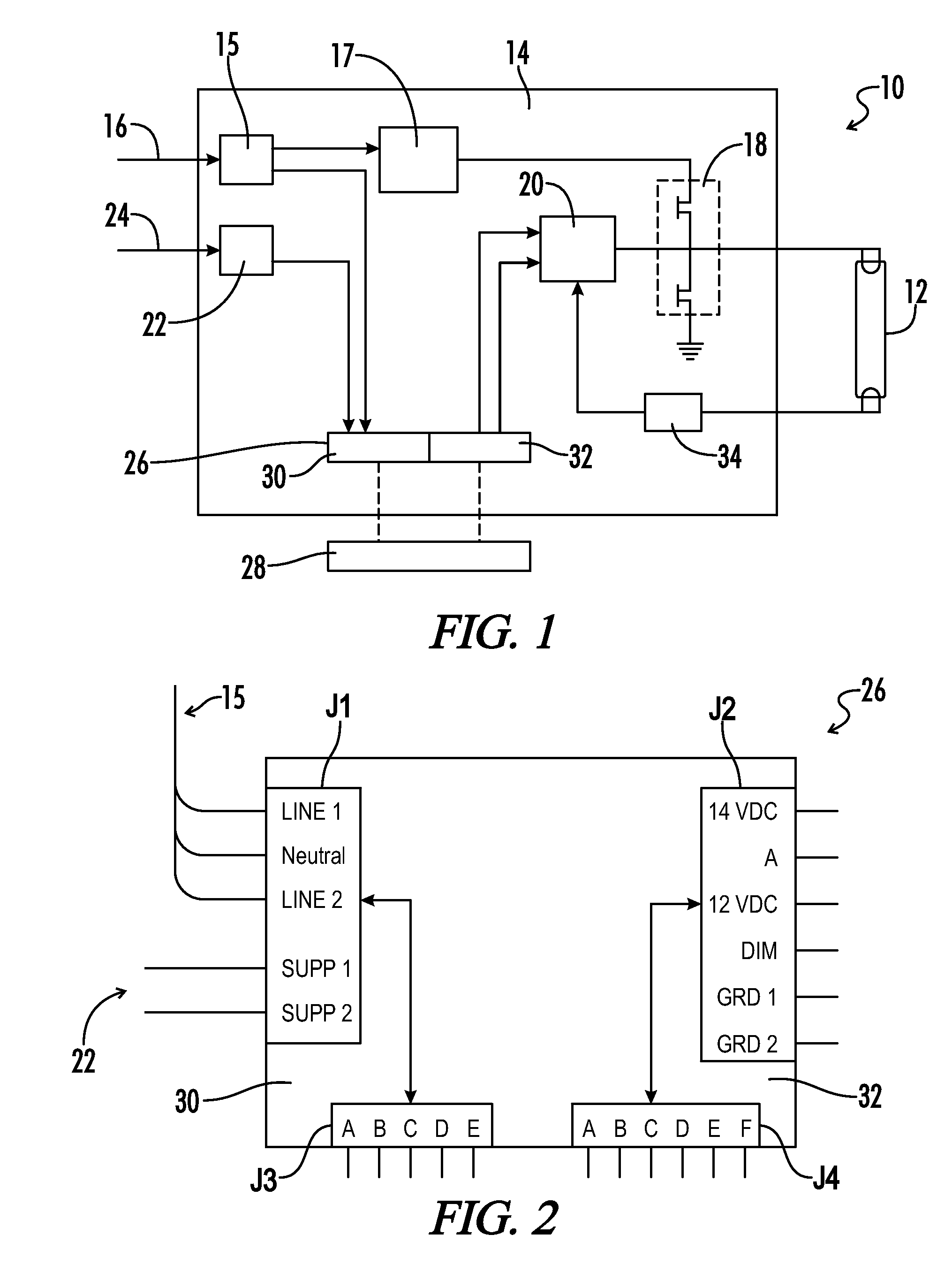
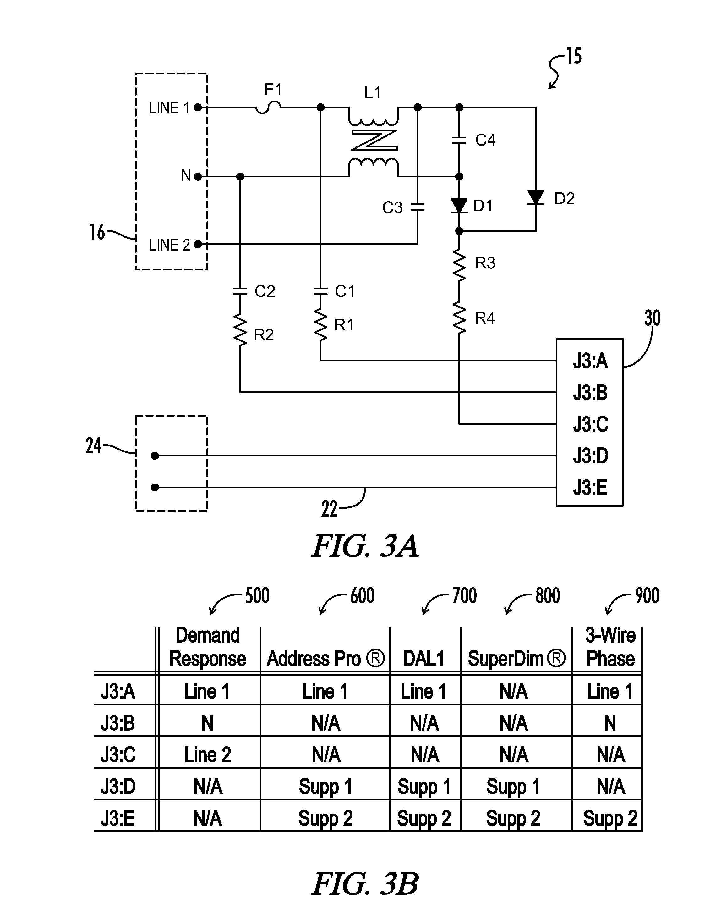
[0032]Referring g...


PUM


Abstract

A modular electronic ballast is provided for powering a fluorescent lamp. A motherboard is configured to receive an AC input signal, one or more supplemental input signals and a feedback signal from the lamp. A ballast control circuit generates an output signal for an oscillating inverter driving the lamps. A daughter card is coupled to the motherboard and selected from a plurality of daughter cards, each configured to provide a dimming control signal having predetermined characteristics and readable by the control circuit. The daughter cards are collectively configured to provide dimming control signals in response to each of a line-coupled demand response interface, one or more digitally addressable interfaces, analog dimming signals received via said supplemental communications bus, and three-wire phase control signals received via said AC line and said supplemental communications bus. The motherboard is configured to interchangeably receive any one of the daughter cards. The ballast control circuit is effective to generate output signals in response to the feedback signal, dimming control signal and a predetermined lamp output value.

Description

CROSS-REFERENCES TO RELATED APPLICATIONS[0001]This application claims benefit of the following patent application: U.S. Provisional Application No. 61 / 096,161, filed Sep. 11, 2008.[0002]A portion of the disclosure of this patent document contains material that is subject to copyright protection. The copyright owner has no objection to the reproduction of the patent document or the patent disclosure, as it appears in the U.S. Patent and Trademark Office patent file or records, but otherwise reserves all copyright rights whatsoever.STATEMENT REGARDING FEDERALLY SPONSORED RESEARCH OR DEVELOPMENT[0003]Not ApplicableREFERENCE TO SEQUENCE LISTING OR COMPUTER PROGRAM LISTING APPENDIX[0004]Not ApplicableBACKGROUND OF THE INVENTION[0005]The present invention relates to dimming and non-dimming electronic ballasts for powering fluorescent lamps. More particularly, the present invention relates to modular designs for various electronic ballast interface protocols making use of a common power mo...

Claims


Application Information

Patent Timeline
Patent Type & Authority Patents(United States)
IPC IPC(8): H05B41/16H05B41/24
CPCH05B41/295
Inventor RADZINSKI, CHRISTOPHERXIONG, WEI
Owner UNIVERSAL LIGHTING TECHNOLOGIES
Why Eureka
Try Eureka